EasyManua.ls Logo

Icom IC-V8000 Service Manual

Icom IC-V8000
34 pages
To Next Page IconTo Next Page
Page #1 background imageLoading...
Page #1 background image
SERVICE
MANUAL
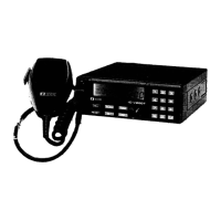
VHF FM TRANSCEIVER
1-1-32, Kamiminami, Hirano-ku, Osaka, 547-0003, Japan
S-13815IZ-C1
© 2002 Icom Inc.

Other manuals for Icom IC-V8000

Questions and Answers:

Icom IC-V8000 Specifications

General IconGeneral
BrandIcom
ModelIC-V8000
CategoryTransceiver
LanguageEnglish

Summary

DANGER

REPAIR NOTES

SECTION 1 SPECIFICATIONS

GENERAL

General technical specifications of the transceiver, including frequency coverage and power.

TRANSMITTER

Detailed transmitter specifications such as output power and modulation.

RECEIVER

Detailed receiver specifications including sensitivity and selectivity.

SECTION 3 DISASSEMBLY AND OPTION INSTRUCTIONS

REMOVING THE COVER

Step-by-step guide for removing the transceiver's outer cover.

REMOVING THE MAIN UNIT

Instructions for safely removing the main internal unit.

REMOVING THE FRONT PANEL

Procedure for detaching the front panel of the transceiver.

SECTION 4 CIRCUIT DESCRIPTION

4-1 RECEIVER CIRCUITS

Describes the radio receiver circuits and their operational principles.

4-1-3 1ST MIXER AND 1ST IF CIRCUITS (MAIN UNIT)

Details the first mixer and intermediate frequency circuits for signal conversion.

4-2 TRANSMITTER CIRCUITS

Details the radio transmitter circuits and their operational principles.

4-1-4 2ND IF AND DEMODULATOR CIRCUITS (MAIN UNIT)

Explains the second IF stage and demodulator circuits for signal processing.

4-1-1 ANTENNA SWITCHING CIRCUIT (MAIN UNIT)

Description of the circuit that switches the antenna between transmit and receive.

4-2-3 DRIVE/POWER AMPLIFIER CIRCUITS (MAIN UNIT)

Explains the circuits responsible for amplifying the RF signal for transmission.

4-1-2 RF CIRCUIT (MAIN UNIT)

Explanation of the RF circuit responsible for signal amplification and filtering.

4-2-4 APC CIRCUIT (MAIN UNIT)

Details the Automatic Power Control circuit for stabilizing output power.

SECTION 5 PARTS LIST

SECTION 6 MECHANICAL PARTS AND DISASSEMBLY

SECTION 9 BLOCK DIAGRAM

SECTION 10 VOLTAGE DIAGRAM

Related product manuals