4 - 8
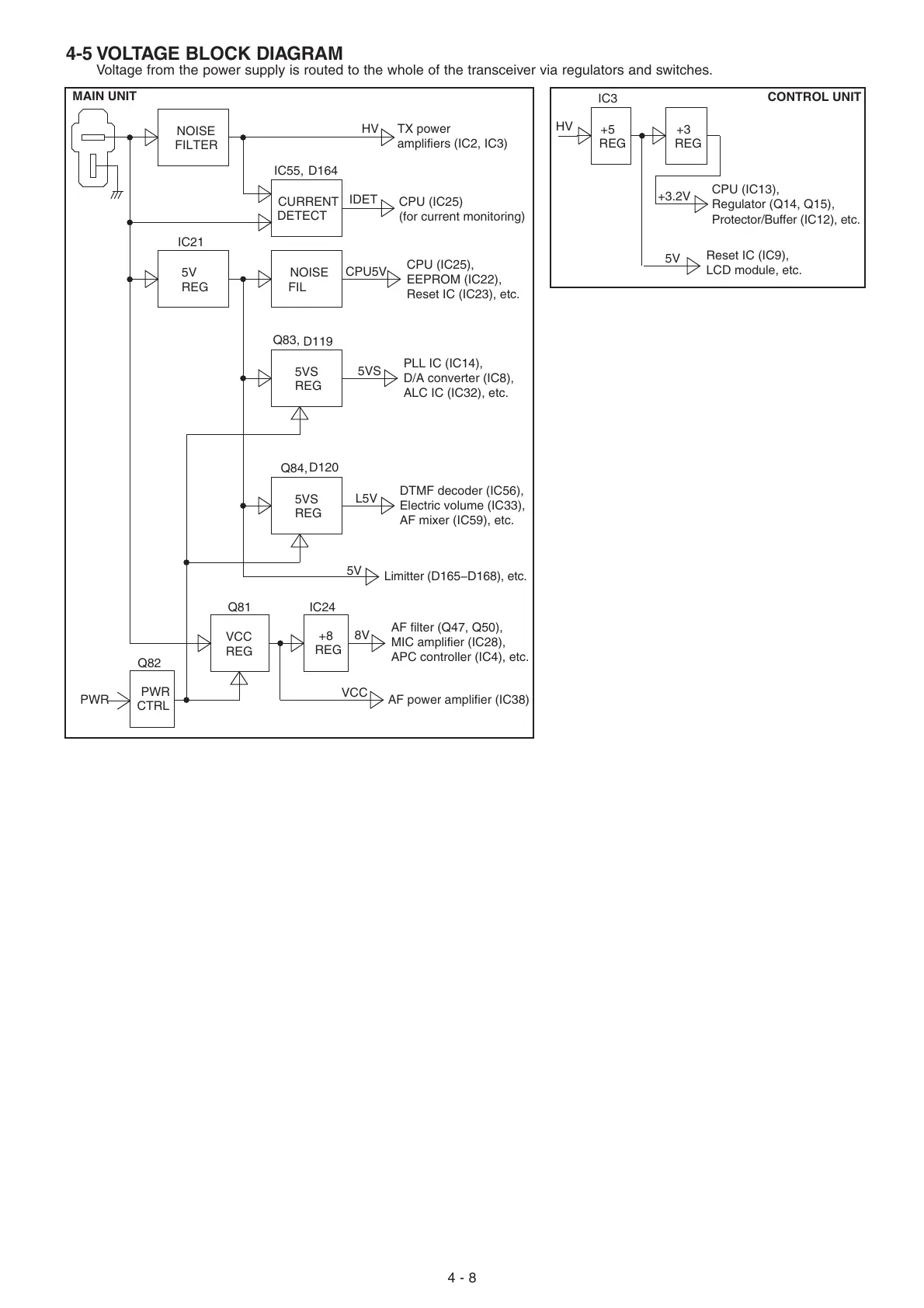
4-5 VOLTAGE BLOCK DIAGRAM
Voltage from the power supply is routed to the whole of the transceiver via regulators and switches.
PWR
CTRL
+8
REG
IC21
Q81
PWR
CPU5V
NOISE
FIL
FILTER
NOISE
CURRENT
DETECT
IDET
HV
HV
TX power
amplifiers (IC2, IC3)
MAIN UNIT
CONTROL UNIT
CPU (IC25)
(for current monitoring)
CPU (IC25),
EEPROM (IC22),
Reset IC (IC23), etc.
PLL IC (IC14),
D/A converter (IC8),
ALC IC (IC32), etc.
VCC
5VS
L5V
8V
IC24
D119
Q83,
Q84,
D120
IC55,
5VS
REG
REG
5VS
5V
5V
REG
D164
Q82
VCC
REG
DTMF decoder (IC56),
Electric volume (IC33),
AF mixer (IC59), etc.
Limitter (D165−D168), etc.
AF filter (Q47, Q50),
MIC amplifier (IC28),
APC controller (IC4), etc.
AF power amplifier (IC38)
IC3
+3
REG
CPU (IC13),
Regulator (Q14, Q15),
Protector/Buffer (IC12), etc.
Reset IC (IC9),
LCD module, etc.
5V
+5
REG
+3.2V

 Loading...


