Do you have a question about the Icom MR-1000TIII and is the answer not in the manual?
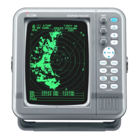
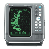
Detailed description of the control panel on the front of the radar unit.
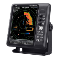
Explanation of various indicators and readouts displayed on the radar screen.
Configuration options for video settings, including tuning, range, and clutter controls.
Settings for radar functions like range rings, waypoints, distance units, and bearings.
Advanced function for tracking targets, calculating CPA and TCPA.
Internal settings for radar operation, including magnetic variation and save time.
Pre-operation checklist and confirmation steps for system connections.
Step-by-step guide on how to power the radar unit on and off.
Function to eliminate echoes caused by rain, snow, or fog, improving clarity.
Function to reduce echoes from sea clutter and waves at close range.
Allows shifting the scanning area to enlarge specific parts of the display.
Reduces interference from other nearby radar systems.
Magnifies target blips electronically for easier identification.
Expands the radar screen display to double the size of targets.
Tracks target movement over time, useful for observing speed and course.
Conserves battery power by pausing scanner transmission at set intervals.
Displays the vessel's speed, requiring NMEA 0183 data input.
Shows ship or cursor latitude and longitude with NMEA 0183 data.
Displays received waypoint data from navigation equipment.
Magnifies target echoes for better visibility, especially at shorter ranges.
Configures bearing type (true/magnetic) and adjusts magnetic variation.
Describes methods for measuring distances using fixed rings and variable range markers.
Explains how to use EBL and VRM controls for precise target bearing and distance measurements.
Details measuring distance, direction, relative speed, and course between targets or waypoints.
Allows setting a defined alarm zone for collision avoidance alerts.
Configures alarm behavior for targets entering or leaving the set zone.
Guides through configuring ATA parameters like target display, vectors, and alarm limits.
Instructions for selecting and tracking targets using the ATA function.
Illustrates how target past positions are displayed as dots to show movement.
Explains false echoes caused by radiation escaping the main beam.
Describes echoes appearing beyond a target due to strong signals.
Discusses limitations on detecting close targets due to pulse length and beam width.
Explains how obstructions create blind spots where targets are not detected.
Details how pulse width and beam width affect the ability to distinguish targets.
Guide for connecting scanner and display units, including NMEA and power.
Specifies acceptable DC power input voltage range for the radar.
Instructions for properly grounding the display unit to prevent electrical issues.
Guidance on selecting a location and mounting the display unit safely.
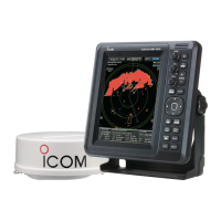
Instructions for installing the EX-2714 radome type scanner unit.
Steps for connecting the system cable to the EX-2714 scanner unit.
Instructions for installing the EX-2780 open array type scanner unit.
Steps for connecting the system cable to the EX-2780 scanner unit.
Details on securely mounting the EX-2780 scanner unit onto its support.
Selection of antenna rotation speed between 48 rpm and 36 rpm.
How to display a test pattern to check CRT distortion.
Enables a simulation mode for testing radar functions without actual transmission.
Procedure to reset all settings to factory defaults.
Option to change the display language for service menus.
Adjusts sweep timing, compensating for cable length variations.
Corrects the heading marker line alignment with the ship's bow.
Sets the pulse rate for the speed sensor unit.
Allows selection of different screen ranges for radar display.
Lists potential error messages and their corresponding conditions and solutions.
General tips for keeping the equipment clean and in good working order.
Specific cleaning and painting instructions for the scanner unit.
Guidance on cleaning the CRT display to maintain picture quality.
Information on available system cables for extending unit separation.
General specifications including range, preheat time, and connection length.
Technical specifications for the EX-2714 (Radome) and EX-2780 (Open array) scanner units.
Technical specifications for the radar display unit, including CRT, pixels, and power.
| Brand | Icom |
|---|---|
| Model | MR-1000TIII |
| Category | Marine Radar |
| Language | English |