Do you have a question about the Icom MR-1010RII and is the answer not in the manual?
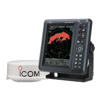
Lists all items included with the marine radar display and scanner unit.
Emphasizes reading instructions, saving the manual, and key features of the radar system.
Defines DANGER, WARNING, CAUTION, and NOTE levels for safety alerts.
Provides specific radar settings to ensure detection of SART signals on the screen.
Lists warnings and cautions for safe operation and handling of the display and scanner units.
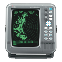
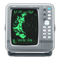
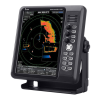
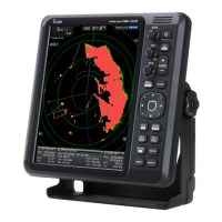
Introduces the radar's front panel layout and its main components.
Details the functions of physical buttons and knobs on the radar's front panel.
Explains the various indicators and readouts displayed on the radar screen.
Describes icons for AIS, ARPA, and other target information displayed on screen.
Details display of own ship data, parallel index lines, and waypoint information.
Explains alarm zones, warning messages, and popup messages shown on the radar screen.
Instructions for turning the radar unit on and off, including warm-up procedures.
Guide to adjusting screen brightness, key backlight, and color settings.
Explains GAIN, SEA, RAIN, and manual tuning for optimal radar display.
Details OFF CENTER, ZOOM, and Interference Rejection (IR) functions for screen adjustments.
Explains functions to enhance target visibility and magnify echoes.
How to use the trail function to visualize target tracks and relative speeds.
Instructions on setting and entering the power save mode to conserve battery power.
How to display ship speed and waypoints received from navigation equipment.
How to set bearing input, type, and magnetic variation for accurate readings.
Explains using fixed rings and parallel index lines for measuring distances to targets.
How to use VRM1 and VRM2 to measure distances and set targets.
Measuring distance/direction between targets and relative speed/course.
How to measure distance and course from a waypoint using EBL/VRM.
How to set up alarm zones to alert when targets enter specific areas.
Configuring zone alarms to trigger when targets enter (IN) or exit (OUT) the set zone.
Steps to acquire and track targets using ARPA for collision avoidance.
Explains ARPA target status icons, predicted course, speed, and vector line interpretation.
Customizing ARPA function settings like auto-acquire, track display, and target numbering.
How to select and display detailed information for selected AIS targets.
Describes icons for different AIS target types and the AIS information box.
Explains status of AIS vessels and their plot trails.
Configuring AIS display, auto-activate, warnings, and target display preferences.
Defines criteria for identifying lost AIS targets and reporting intervals.
Managing safety messages and setting favorite AIS targets within a specified range.
How the radar plots and displays received DSC information from other vessels.
Marking targets on display or outputting data using the Target Latitude/Longitude (TLL) function.
How to select the display language and use the radar's simulation mode.
Setting antenna rotation speed and adjusting sweep timing for accurate echo display.
Manually adjusting the heading marker to align with the vessel's bow direction.
Customizing which radar ranges are selectable and displayed.
Saving and loading different operational settings for various situations.
How to perform a Setting Reset or Factory Reset to restore default configurations.
How to navigate and use the radar's menu system interface.
Customizing display colors, echo steps, and brilliance of various screen elements.
Configuring target display, ARPA parameters, and clear target functions.
Configuring AIS display, auto-activate, warnings, and target display preferences.
Adjusting video settings like dynamic range, IR, echo stretch, pulse width, and SEA curve.
Configuring system-wide settings like backlight, alarms, save time, and bearing reference.
Setting display units, language, bearing input, TX inhibit, and range settings.
Displaying own vessel's AIS information and system status indicators.
Monitoring input/output port status and scanner operational status.
Explains phenomena causing false echoes from sidelobes and indirect reflections.
Discusses multiple echoes and factors affecting minimum detection range.
Explains how obstructions create blind or shadow sectors, hindering target detection.
Defines distance and direction resolution based on pulse width and beam width.
Basic cleaning and checks to ensure the radar's continued reliable operation.
Cleaning and mounting checks for the radar scanner unit.
Cleaning procedures for the display unit's LCD screen to maintain picture clarity.
Lists common error messages for the radar system and their conditions.
Lists potential error messages related to the AIS unit and their causes.
Details general specifications for the radar system, including range and power.
Lists specifications for the display unit, such as LCD type, resolution, and dimensions.
Outlines the technical specifications for the EX-2714 scanner unit.
Lists optional units like system cables and video output units.
Details required external data inputs (bearing, speed, position) for radar functions.
Instructions for connecting the display unit, scanner unit, and power supply.
Guidance on selecting a location and mounting the display unit for optimal viewing.
Step-by-step instructions for mounting the display unit to a wall or instrument panel.
Guidelines for selecting a location and securely mounting the EX-2714 scanner unit.
Detailed steps for wiring the system cable, power cable, and ground wire to the scanner unit.
Instructions for installing the optional UX-252 unit to connect an external display.
A checklist to ensure all installation steps are completed correctly before powering on.
| Power Supply | 12/24 V DC |
|---|---|
| Antenna Rotation Speed | 24 rpm |
| Frequency | 9410 MHz ±30 MHz |
| Antenna Length | 1.2 m (3.9 ft) |
| Display Size | 10.4 inch |
| Power Consumption | 48 W (approx.) |
| Operating Temperature | -15°C to +55°C |
| Output Power | 4 kW (peak) |
| Range Scales | 0.25, 0.5, 0.75, 1.5, 3, 6, 12, 24, 48 nm |