14
INSTALLATION AND CONNECTIONS
54
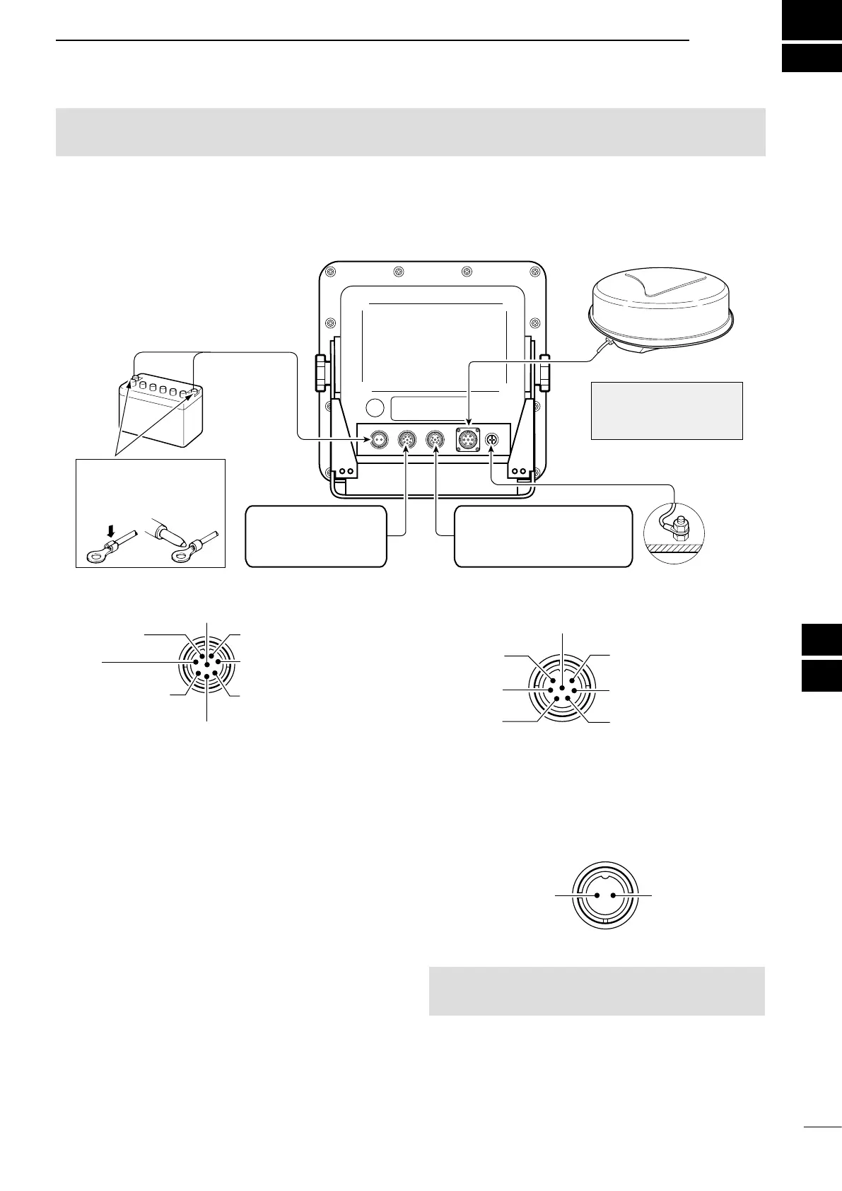
■ Connecting the units
NMEA2:
NMEA 0183 data input/output
+
Ground
Power supply
10.2 to 42 V DC
Red:
Black: _
PWR
GND
NEVER connect
anything other than the
supplied Scanner unit.
Supplied Scanner unit
Display unit
NOTE: Use the termi-
nals shown below for the
cable connections.
Solder
Crimp
NMEA1:
AIS data input
Bearing data input
NMEA 1/2 inputs/NMEA 2 output/DSC input: 4800 bps, AIS input: IEC61162-2 38400 bps
■ Ground connection
To prevent electrical shocks and other problems, ground the display unit through the [GND] terminal. For best
results, connect a heavy gauge wire or strap to the nearest grounding point on the vessel. The distance between
the [GND] terminal and the ground point should be as short as possible.
■ Power source requirement
D DC power source
The display unit is designed for connection to
any power source with a voltage of 10.2–42 V
DC, so that a 12, 24, or 32 V DC battery can be
used without a DC-DC converter or any internal
modications.
• DC power cable connection
Connect the supplied DC power cable as shown in
the diagram.
(Rear panel view)
CAUTION: An incorrect cable connection will
damage the display unit.
NMEA1 connection (Rear panel view)
q AIS input (+)
w NC
i GND
r NMEA 1 input (–)
or AUX input (–); DATA
e NMEA 1 input (+)
or AUX input (+); DATA
u AIS input (–)
y N+1 input (–)
or AUX input (–); CLOCK
t N+1(+); data input
or AUX input (+); CLOCK
NMEA2 connection (Rear panel view)
q NMEA 2
output (+)
w NMEA 2
output (–)
e NMEA 2
input (+)
u GND
y DSC input (–)
t DSC input (+)
r NMEA 2 input (–)
1
2
3
4
5
6
7
8
9
10
11
12
13
14
15
16
17
18
19
20
21
CAUTION! DO NOT turn ON the display unit before both the display unit and the scanner unit is
completely installed and connected.
 Loading...