56
14
INSTALLATION AND CONNECTIONS
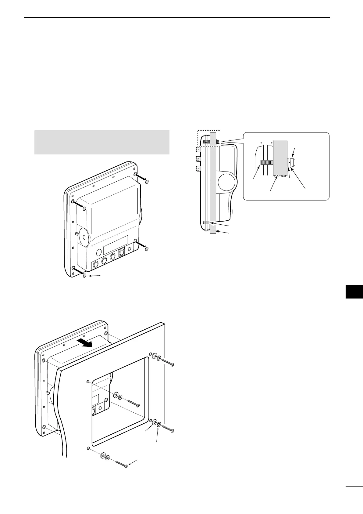
D Wall Mounting
The display unit can be mounted to a at surface,
such as an instrument panel, using the M6 mounting
bolts.
1. Remove the four screw hole seals from the four
corners of the display unit.
BE CAREFUL! NEVER use your nger nail to
remove the seal. Otherwise, you may injure your
nail.
Screw hole seal
2. Using the display unit template that comes
with the display unit, carefully cut a hole in the
instrument panel, or wherever you plan to mount
the display unit.
M6 mounting bolt
Spring washer
Flat
washer
3. Drill four holes for the mounting screw.
L The screw hole depth is 14.5 mm (
9
/
16
inches).
4. Slide the display unit through the hole.
5. Attach the four corners of the display unit
using the flat washers, spring washers, and M6
mounting bolts.
L Select the mounting bolts of the length that ts the
thickness of the instrument panel.
Screw hole depth: 14.5 (
9
/
16
)
Instrument panel
Screw hole
Side view
Instrument panel
Screw hole
Spring washer
Flat
washer
M6 mounting bolt
Unit: mm (inch)
1
2
3
4
5
6
7
8
9
10
11
12
13
14
15
16
17
18
19
20
21
 Loading...