9
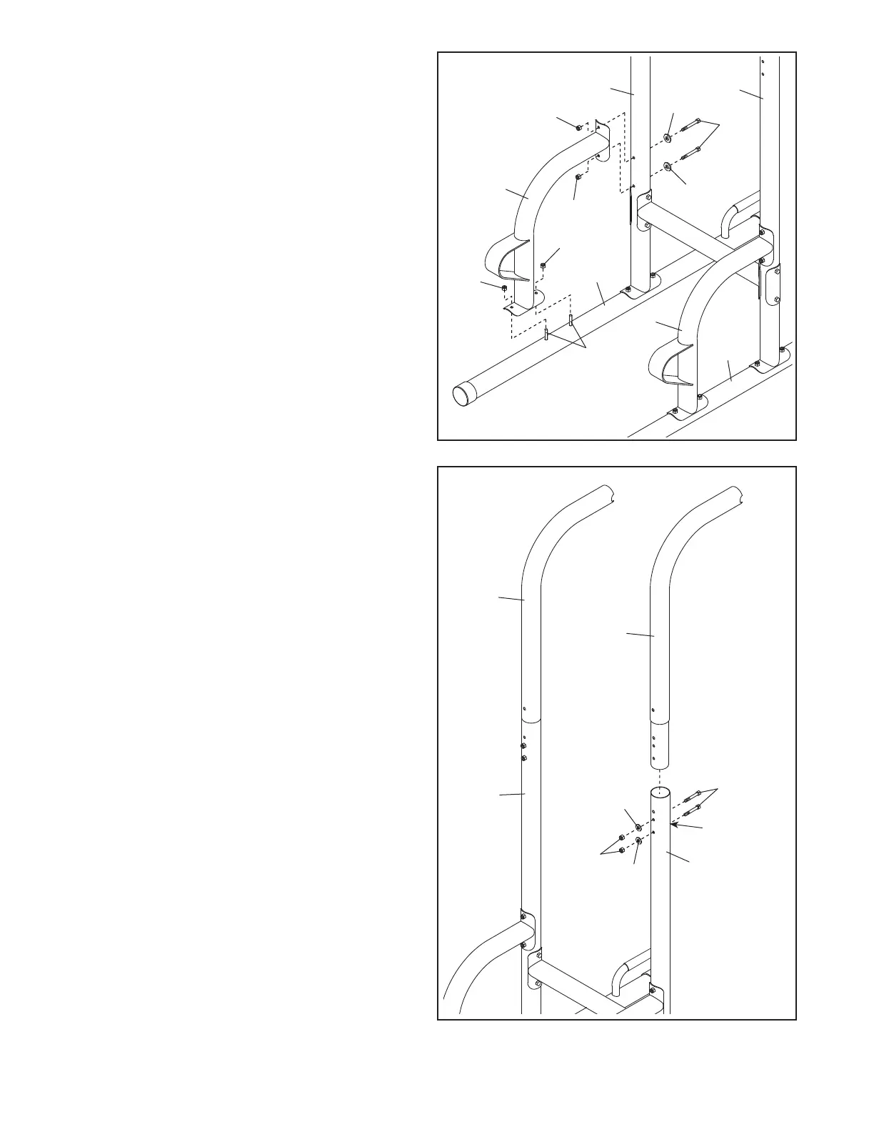
6. Orient one of the Pull-up Frames (3) as shown,
and insert it into one of the Uprights (2). Attach
the Pull-up Frame with two M8 x 68mm Bolts
(24), two M8 Curved Washers (23), and two
M8 Locknuts (22). Note: The Bolts must be
inserted into the lowest set of holes in the
Pull-up Frame and the Upright. Make sure
that the bolt heads are in the hexagonal
holes (C) in the Upright. Do not tighten the
Locknuts yet.
Attach the other Pull-up Frame (3) to the
other Upright (2) in the same way.
3
3
2
6
2
22
23
23
24
5. Attach a Footrest Frame (4) to one of the Bases
(1) with the two indicated M8 x 68mm Carriage
Bolts (20) and two M8 Locknuts (22); do not
tighten the Locknuts yet.
Next, attach the Footrest Frame (4) to the
Upright (2) with two M8 x 75mm Bolts (17), two
M8 Curved Washers (23), and two M8 Locknuts
(22); do not tighten the Locknuts yet.
Attach the other Footrest Frame (4) to the
other Base (1) and the other Upright (2) in the
same way.
5
1
1
22
22
20
17
23
23
22
22
2
4
2
4
C
 Loading...