Two- Stage Multi Position Furnace
Service
Manual
9
440 08 2002 02
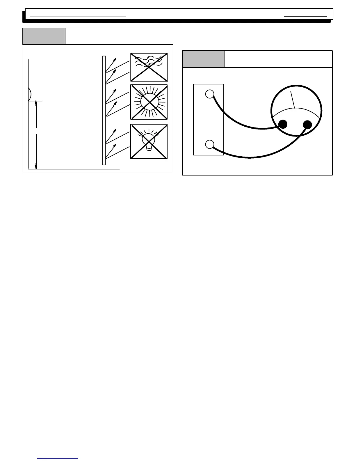
Thermostat Location
Figure 9
5 ft.
DRAFTS
SUN
THERMOSTAT
LIGHT
SHIELD
LOCATION
The thermostat should not be mounted where it may be af-
fected by drafts, discharge air from registers (hot or cold), or
heat radiated from the sun of appliances. Never install in al-
coves, bathrooms or bedrooms.
The thermostat should be located about 5 ft. above the floor
in an area of average temperature, with good air circulation.
Normally, an area in close proximity to the return air grille is
the best choice.
Mercury bulb type thermostats MUST be level to control tem-
perature accurately to the desired set--point. Electronic digi-
tal type thermostats SHOULD be level for aesthetics.
HEAT ANTICIPATORS
Heat anticipators are small resistance heaters built into most
electric--mechanical thermostats. Their purpose is to pre-
vent wide swings in room temperature during furnace opera-
tion.
In order to accomplish this, the heat output from the anticipa-
tor must be the same regardless of the current flowing
through it. Consequently, most thermostats have an adjust-
ment to compensate for varying current draw in the thermo-
stat circuit.
The proper setting of heat anticipators then is important to
insure proper temperature control and customer satisfac-
tion.
The best method to obtain the required setting for the heat
anticipator, is to measure the actual current draw in the con-
trol circuit (“W”) using a low range (0--2.0 Amps) Ammeter.
(See Figure 10) After measuring the current draw, simply
set the heat anticipator to match that value.
Measuring Current Draw
Figure 10
Ammeter
W
R
Subbase
Amps
If a low range ammeter is not available, a “Clamp--on” type
meter may be used as follows:
1. Wrap EXACTLY ten (10) turns of wire around the jaws
of a clamp--on type ammeter .
2. Connect one end of the wire to the “W” terminal of the
thermostat sub--base, and the other to the “R” termi-
nal.
3. T urn power on, and wait approximately 1 minute, then
read meter.
4. Divide meter reading by 10 to obtain correct anticipator
setting.
NOTE: For 2 Stage heating thermostats the above proce-
dure MUST be perf ormed twice. O nce f or first
st age ( W
1), and once for second st age (W2), if
both stages have adjustable heat anticipators.
If an ammeter is not available, a setting of 0.10 amps may
be used for models equipped with the HONEYWELL
SV9541Q Gas Valve/Ignition Control. They should, howev-
er, provide satisfactory operation in most cases.
Electronic thermostats do not use a resistance type anticipa-
tor. These thermostats use a microprocessor (computer)
that determines a cycle rate based on a program loaded into
it at the factory.
These cycle rates are normally field adjustable for different
types to equipment. The method of adjustment, however,
varies from one thermostat manufacturer to another. Check
with the thermostat manufacturer to find out the proper way
of adjusting the cycle rate.