Two- Stage Multi Position Furnace
Service
Manual
12
440 08 2002 02
14. PRESSURE SWITCHES
TRANSITION PRESSURE SWITCH
Under normal operating conditions, sufficient pressure is de-
veloped by the exhaust (combustion) blower to close the
switch, and permit the burner to operate. As the condensate
drain begins to back--up, however , the pressure begins to re-
duce. When the pressure drops sufficiently, burner operation
will be prevented until the condition is corrected.
STANDARD PRESSURE SWITCHES - ALL
MODELS
Model
Max.
Close
Open Part #
Condensing
50, 75 &100
--1.70² W.C.
--1.50 + 0.10² W.C.
--
125
--2.00² W.C.
--1.80 + 0.10² W.C.
--
Always check current “Technical Support Manual”for
Part Nos.
BLOWER PRESSURE SWITCH
An air proving switch (pressure switch) is used on all models
to insure that a draft has been established through the heat
exchanger before allowing burner operation.
To insure continued SAFE, RELIABLE, operation, NEVER
SUBSTITUTE a pressure switch with one that is similar in
appearance. ONLY FACTOR Y PROVIDED or
AUTHORIZED SUBSTITUTES ARE ACCEPTABLE.
All models installed at altitudes of 4,000¢ above sea level or
higher require replacing the standard pressure switch with a
high altitude pressure switch. The different pressure switch
settings allow continued SAFE, RELIABLE, high altitude
operation.
Note: T ransition switch checks lo--fire airflows & blocked
condensate. Blower switch checks Hi--fire airflow.
HIGH ALTITUDE PRESSURE SWITCHES - ALL
MODELS
Model
Max.
Close
Open Part #
Condensing
50, 75 &100
--1.40² W.C.
--1.20 + 0.10² W.C.
--
1013165
125
--1.70² W.C.
--1.50 + 0.10² W.C.
--
1013157
Always check current “Technical Support Manual”for
Part Nos.
Under normal operating conditions, sufficient negative pres-
sure will be created to close the pressure switch, and keep
it closed to keep furnace operating. Under abnormal condi-
tions, however , such as a restricted vent pipe, or a leak in one
of the heat exchangers, sufficient negative pressure will not
be created. This will result in the switch failing to close or fail-
ing to remain closed during furnace operation.
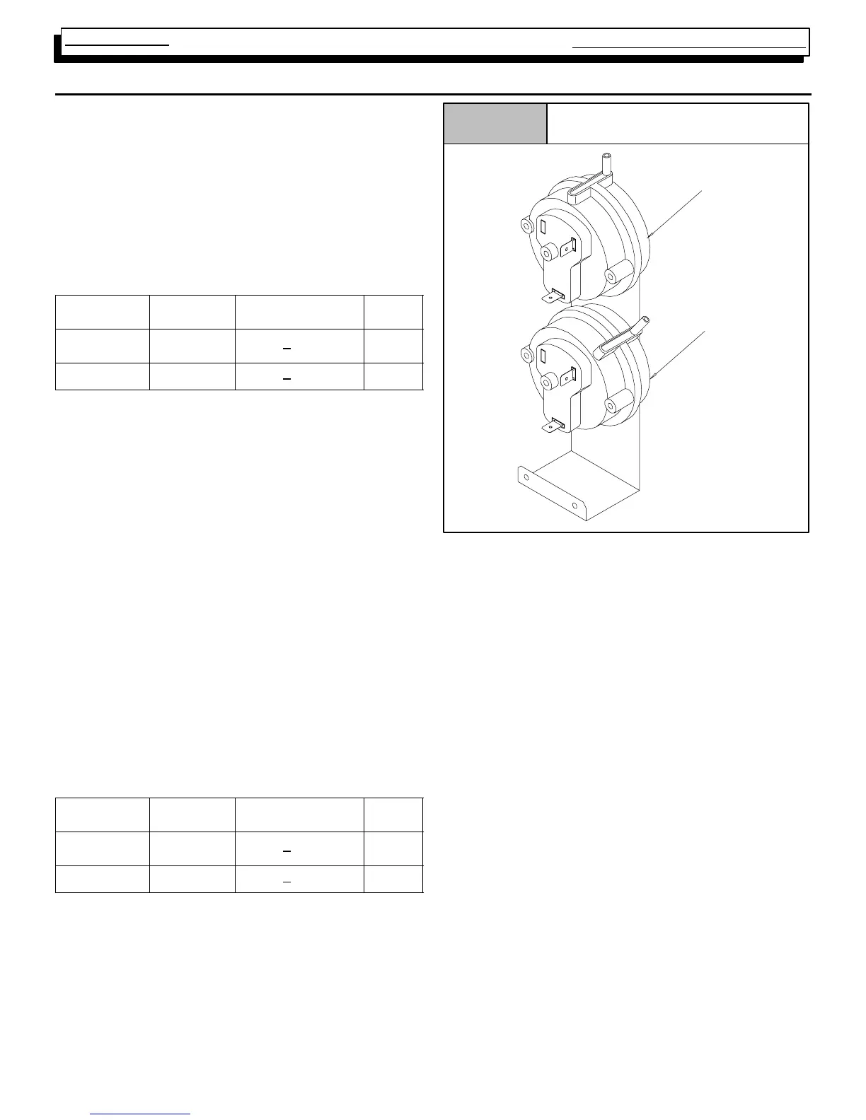
Pressure Switches
Figure 13
25--23--72
T ransition
(Lo--fire)
Blower
(Hi--fire)
When servicing a unit whose pressure switch will not close,
or remain closed during operation, the operating pressure of
that furnace should be checked and compared to
approximate operating pressures listed in Table 3 and the
switch setting(s) listed above for the model family you are
servicing.
It is important to remember , that greater negative pressures
are created by the furnace when “Hot” (I.E. upon initial start--
up) than when “Cold” (I.E. after furnaces has been in opera-
tion for a few minutes). Because of this, furnace pressure
should ONLY be checked when “HOT” to insure accurate
readings.
Table 3 lists approximate operating pressures for Direct
Vent (I.E. Two Pipe) installations of models in this series.
They were obtained in a test lab, under controlled conditions
using two (2) specific vent lengths. They are included in this
manual to provide you with a “Barometer” to gauge our pres-
sures against. The pressures you obtain in the field will differ
slightly from these figures based upon vent length, gas pres-
sure, operating temperature, etc.
Major discrepancies in pressures, will normally cause
problems with pressure switch operation. These Major dis-
crepancies should be investigated as follows: