Two- Stage Multi Position Furnace
Service
Manual
45
440 08 2002 02
AL WAYS CHECK CURRENT TECHENICAL SUPPORT MANUAL
Circulation Air Blower Data - *9MPV(A1 & A2)
Heating, Cooling & Continuous Airflow Settings
Continuous Blower (CFM) @ 0.10²
²²
² Static
Switch Settings
Furnace Model
#1 #2 50K 75K 100K 125K
0* 0* 540 540 700 703
0 1 660 660 860 821
1 0 780 780 1020 1000
1 1 900 900 1180 1160
*Factory Setting
Hi Heat Air Temperature Adjustment (°
°°
° F)**
Switch Settings
Furnace Model
#3 #4 #5 50K 75K 100K 125K
0** 0** 0** 0 0 0 0
0 0 1 3 2 3 2
0 1 0 6 4 5 6
0 1 1 14 6 9 11
1 0 0 17 11 13 13
1 0 1 -- 8 -- 4 -- 4 -- 5
1 1 0 -- 1 3 -- 4 -- 7 -- 5
1 1 1 -- 1 7 -- 4 -- 9 -- 5
*Factory setting
**Approximate air temperature change from factory setting @ 0.20² static
on high heat ).
Lo Heat Air Temperature Adjustment (°
°°
° F)**
Switch Settings
Furnace Model
#3 #4 #5 50K 75K 100K 125K
0** 0** 0** 0 0 0 0
0 0 1 1 1 1 6
0 1 0 4 2 2 8
0 1 1 7 3 5 12
1 0 0 11 6 8 16
1 0 1 -- 7 -- 4 -- 5 -- 1
1 1 0 -- 1 1 -- 6 -- 9 -- 4
1 1 1 -- 1 5 -- 9 -- 1 1 -- 7
*Factory setting
**Approximate air temperature change from factory setting @ 0.20² static
on high heat ).
Cooling (CFM) @ 0.50²
²²
² Static
Switch Settings
Furnace Model
#6 #7 #8 50K 75K 100K 125K
0* 0* 0* 1170 1395 2095 2059
0 0 1 1098 1 197 1875 1859
0 1 0 991 1096 1642 1700
0 1 1 894 1000 1489 1621
1 0 0 807 907 1255 1410
1 0 1 697 799 1013 1 191
1 1 0 621 650 830 986
1 1 1 556 543 750 800
*Factory setting
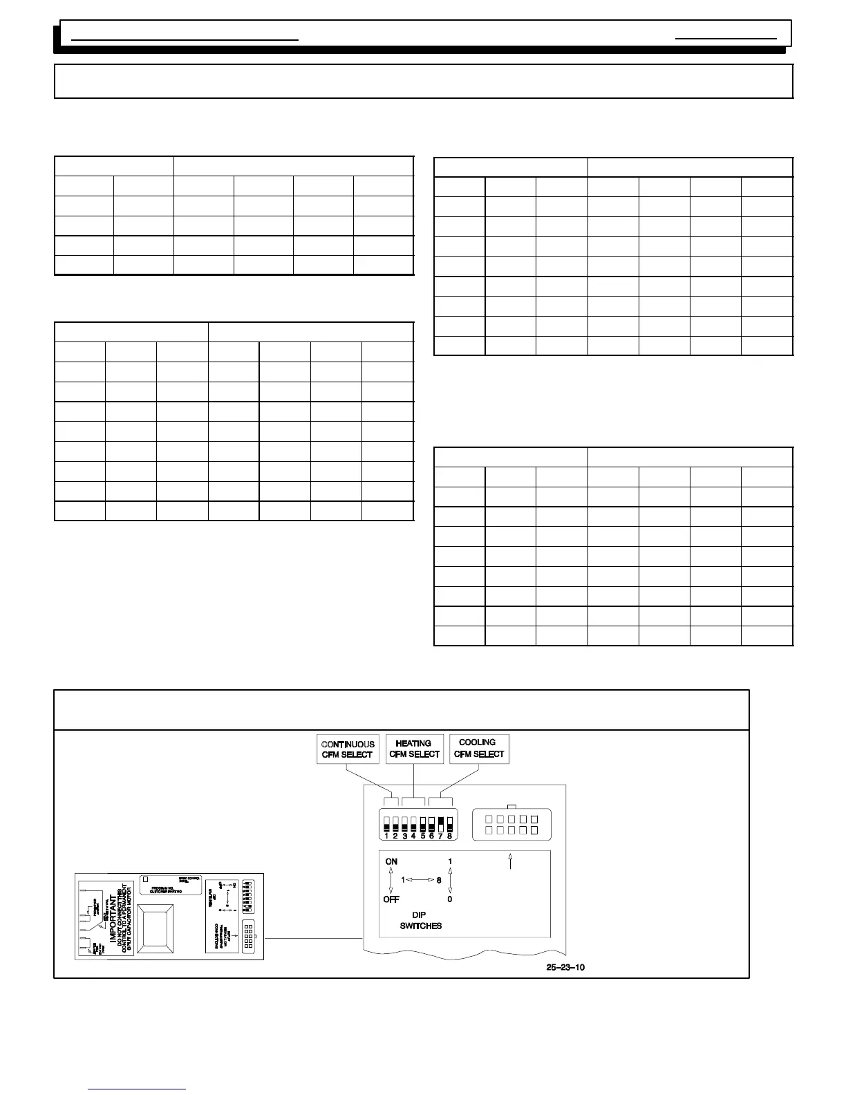
*EXAMPLE
Cooling Airflows Switches
6, 7 & 8:
000 3.5 T on
001 3.0 T on
010 2.5 T on
011 2.0 Ton
*See “Technical Support
Manual” for correct airflow
rates.
010
Blower Motor Settings
INPUT
SIGNAL OR
THERMOSTAT
CONNECTIONS