Two- Stage Multi Position Furnace
Service
Manual
2
440 08 2002 02
1. INTRODUCTION
This service manual is designed to be used in conjunction
with the installation manual and/or technical support manual
provided with each furnace.
These furnaces represent the very latest in high efficiency
gas furnace technology. Consequently, they incorporate the
use of certain controls that contain highly sophisticated elec-
tronic components which are not user serviceable. there-
fore, it is essential that only competent, qualified, service
personnel attempt to install, service, or maintain this prod-
uct.
This Service manual was written to assist the professional
HVAC service technician to quickly and accurately diagnose
and repair any malfunction of this product.
This service manual covers several different models in two
(2) families of our new multi--position furnaces; Variable
Speed (D.C.-- Blower Motor) models in the Condensing fur-
nace family, and 2 speed (P.S.C.--Blower Motor) models in
both the Condensing and Non--Condensing furnace families.
The overall operation of all of these models and families is
essentially the same, with the exception of the Blower Motor,
and/or certain control functions which may be unique to a
particular model and/or family.
This manual, therefore, will deal with all subjects in a general
nature (I.E. all text will pertain to all models) unless that sub-
ject is unique to a particular model or family, in which case
it will be so indicated.
Throughout the manual references may be made to “VARI-
ABLE SPEED MODELS” as well as “TWO SPEED MOD-
ELS”. GENE RALLY, t he distinc t ion between thes e two
groups is based on a difference in the type of Blower Motor
used. T hese may not be the only diff erenc es, however,
and the differences may vary from model to model within a
particular family or series.
It will be necessary then for you to accurately identify the
unit you are servicing, so you may be certain of a proper
diagnosis and repair. (See Unit Identification, Page 3)
The information contained in this manual is
intended for use by a qualified service technician
who is familiar with the safety procedures required
in installation and repair and who is equipped with
the proper tools and test instruments.
Installation or repairs made by the unqualified
persons can result in hazards subjecting the
unqualified person making such repairs to the risk of
injury or electrical shock which can be serious, or
even fatal not only to them, but also to persons being
served by the equipment.
If you install or perform service on equipment, you
must assume responsibility for any bodily injury or
property damage which may result to you or others.
We will not be responsible for any injury or property
damage arising from improper installation, service
and/or service procedures.
!
2. UNIT IDENTIFICATION
The unit’s rating plate contains important information for the
service technician. It also lists the complete Model Manufac-
turing and Serial Numbers.
These complete numbers are required to obtain correct re-
placement parts (example, in certain model families a unit
having a MARKET REVISION of “C” is likely to be equipped
with one or more different components.
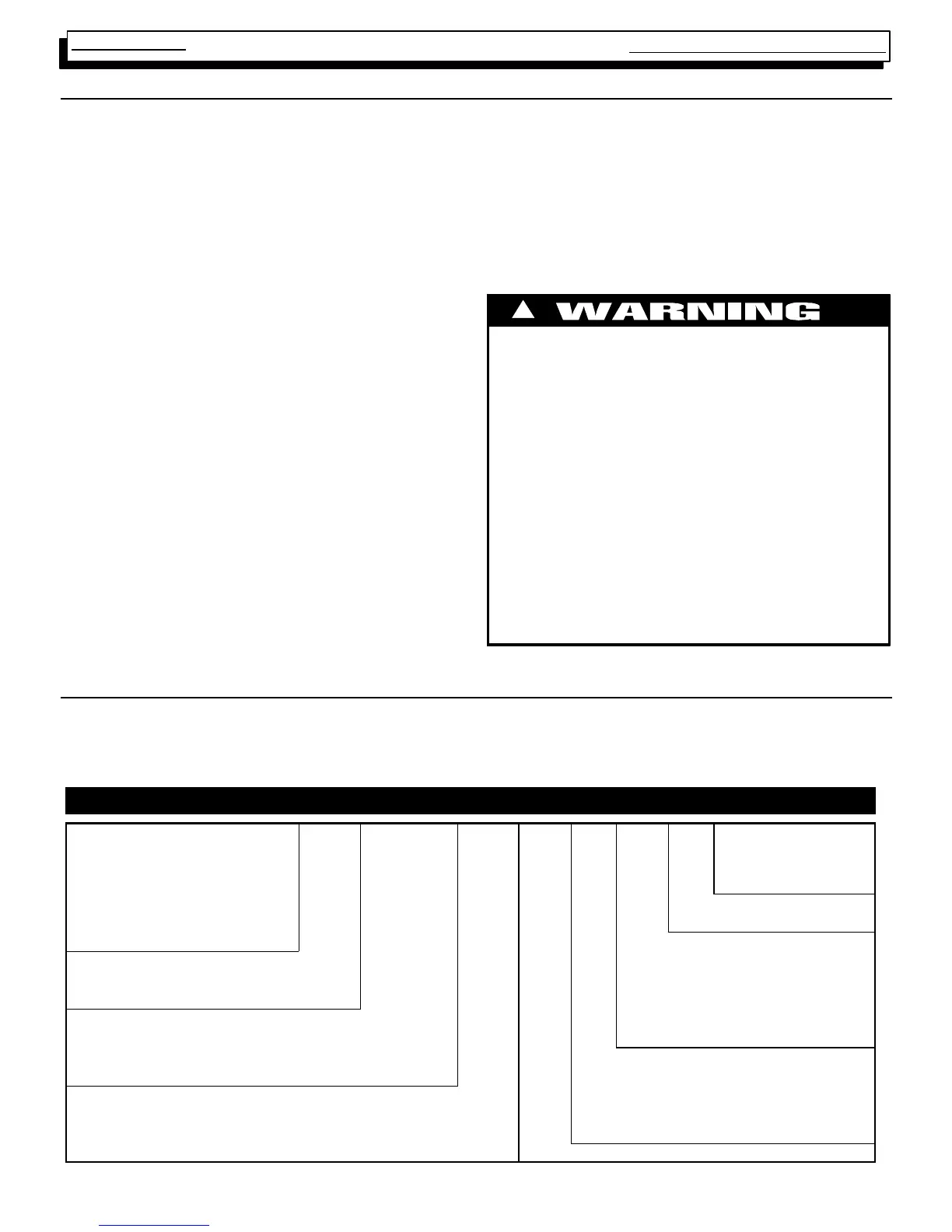
MODEL NUMBER IDENTIFICATION GUIDE
* 9 MP T 075 B 12 A 1
Brand Identifier Engineering Rev.
T=Tempstar N=Neture Denotes minor changes
C = Comfortmaker/Keeprite Marketing Digit
H = Heil/Arcoaire X = Evaluation Denotes minor change
Cooling Airflow
Brand Identifier 08 = 800 CFM
8 = Non--Condensing, 80+% Gas Furnace 12 = 1200 CFM
9 = Condensing, 90+% Gas Furnace 14 = 1400 CFM
Installation Configuration 16 = 1600 CFM
UP = Upflow DN = Downflow UH = Upflow/Horizontal 20 = 2000 CFM
HZ = Horizontal DH = Downflow/Horizontal Cabinet Width
MP = Multiposition, Upflow/Downflow/Horizontal B = 15.5² Wide
Major Design Feature F = 19.1² Wide
1 = One (Single) Pipe L= Low NOx T = Two Stage J = 22.8² Wide
2 = Two Pipe N = Single Stage V = V ariable Speed L = 24.5² Wide
D = 1 or 2 Pipe P = PVC Vent Input (Nominal MBTUH)