Two- Stage Multi Position Furnace
Service
Manual
17
440 08 2002 02
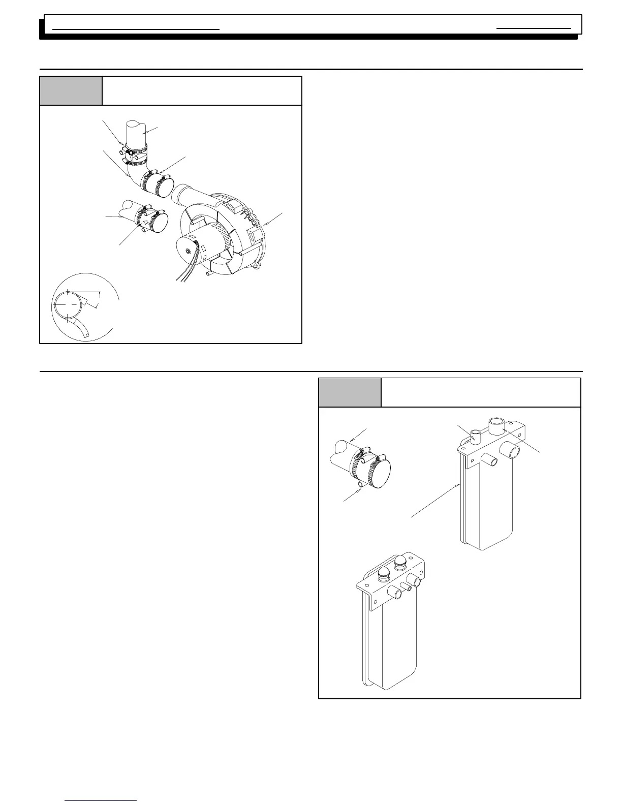
18. EXHAUST BLOWER
Figure 25
Exhaust Blower
Vent Pipe (Top panel exit)
Rubber Coupling & Clamps
90° Elbow
Blower
Vent Fitting
&Clamps
Vent Pipe
(Side panel exit)
Vent Fitting
&Clamps
25--23--35
DRAIN SIDE VIEW
C
L
Rotate
downward
20° to 30°
Always check the current “Technical Support Manual” for
part nos.
19. CONDENSATE DRAIN TRAP
This furnace removes both sensible and latent heat from the
products of combustion. Removal of the latent heat results in
condensation of the water vapor. The condensate is re-
moved from the furnace through the drains in the plastic tran-
sition and the vent fitting. The drains connect to the external-
ly mounted condensate drain trap on the left or right side of
the furnace. Refer to Figure 26.
The condensate drain trap supplied with the furnace MUST
be used. The drain line between the condensate drain trap
and the drain location must be constructed of
3
/
4
² PVC or
CPVC pipe.
The drain line must maintain a
1
/
4
² per foot downward slope
toward the drain.
DO NOT trap the drain line in any other location than at the
condensate drain trap supplied with the furnace.
If possible DO NOT route the drain line where it may freeze.
The drain line must terminate at an inside drain to prevent
freezing of the condensate and possible property damage.
1. A condensate sump pump MUST be used if required
by local codes, or if no indoor floor drain is available.
The condensate pump must be approved for use with
acidic condensate.
2. A plugged condensate drain line or a failed condensate
pump will allow condensate to spill. If the furnace is
installed where a condensate spill could cause dam-
age, it is recommended that an auxiliary safety switch
be installed to prevent operation of the equipment in
the event of pump failure or plugged drain line. If used,
an auxiliary safety switch should be installed in the R
circuit (low voltage) ONLY.
Figure 26 External Drain Trap
Vent Drain Connection
Drain Line
(hidden)
Transition
Box Drain
25--23-- 63
Vent Drain
Vent Pipe
(Side panel exit)
OLD
NEW