Two- Stage Multi Position Furnace
Service
Manual
42
440 08 2002 02
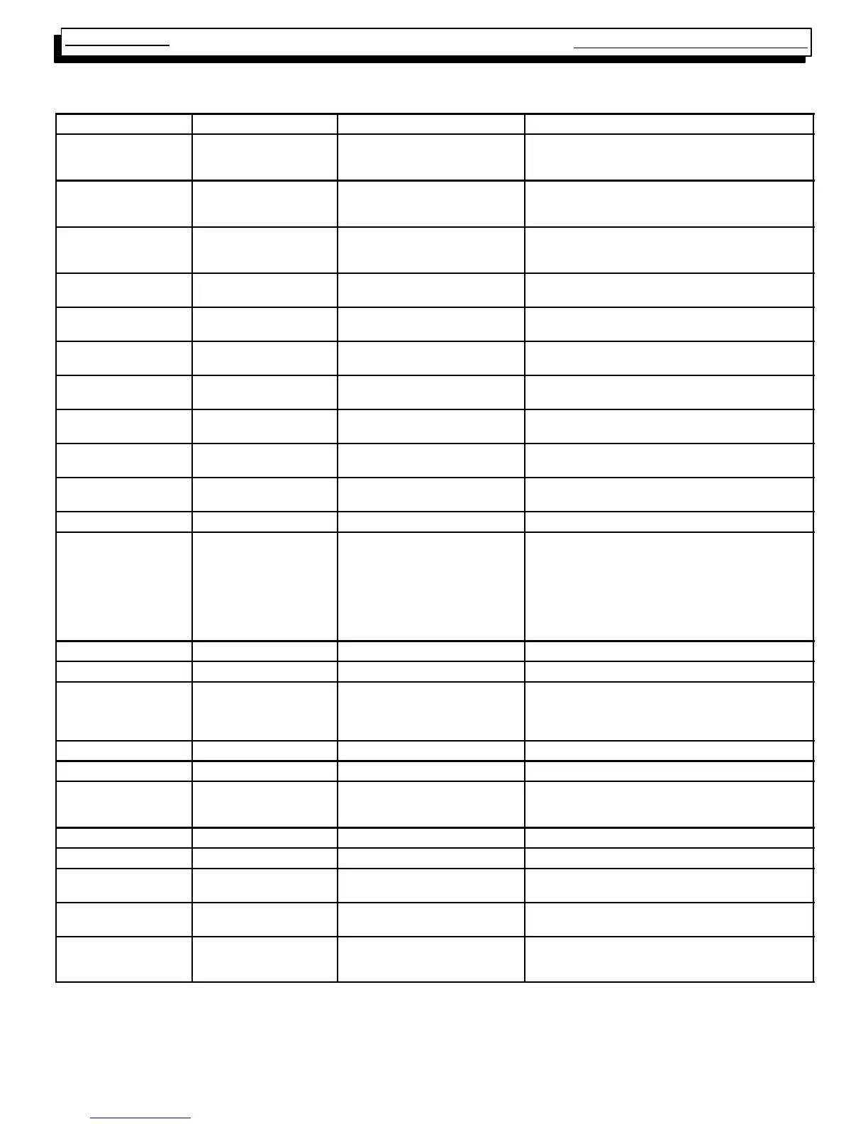
SV9541Q ELECTRICAL VARIATION
2--STAGE
Connector (Pin #) Description Voltage Signal When Signal is Present
Neutrals
(5--
1
/
4
² QC’s)
Neutral 0VAC
(Neutral and earth ground should
be at the same potential)
Always present
120 VAC Line,
XFMR, DC MTR
(3--
1
/
4
² QC’s)
Line Voltage 115 VAC Present when blower door interlock switch is closed.
HEAT LOW
(
1
/
4
² QC’s)
Fan power *115 VAC Present when Low Heat fan speed is on (G request,
Low Heat (W1) mode after Heat Fan On Delay, Heat
Fan Off Delay)
HEAT HIGH
(
1
/
4
² QC’s)
Fan power *115 VAC Present when High Heat fan speed is on (High Heat
(W1 & W2) mode, Open Limit mode).
COOL
(
1
/
4
² QC’s)
Fan power *115 VAC Present when Cool fan speed is on (Cool (Y) mode.
EAC
(
1
/
4
² QC’s)
Electronic Air--
Cleaner power
115 VAC Present when High Heat, Low Heat or Cool fan speed is
on.
CONSTANT FAN
(
1
/
4
² QC’s)
Continuous Fan
power
*115 VAC Present when other fan speeds are on.
IND IN
(
1
/
4
² QC’s)
Inducer motor power from
Smart Valve
Ô
115 VAC Present when Induced draft blower motor is on (Heat
modes, Open Limit mode).
IND LOW
(
3
/
16
² QC’s)
Inducer motor power from
Smart Valve
Ô
115 VAC Present when Induced draft blower motor is on (Heat
modes, Open Limit mode).
HUM
(
1
/
4
² QC’s)
Humidifier power 115 VAC Present when the High Heat or Low Heat fan speeds
are on.
P1 (pin 1) Neutral 0VAC Always present
P1 (pin 2) High Fire solenoid supply
(connects to one side of
high pressure switch
24VDC(lowfire)
16VDC (high fire)
Voltage is always present when 24 VAC transformer is
powered. The signal is actually
1
/2
wave rectified AC
riding on top of DC voltage. The DC voltage readings
given are approximate when measured with a Fluke 79
digital multimeter (or equivalent). To achieve high fire
(energize the high fire solenoid), the high pressure
switch must be closed and the ST9162 fan board must
turn on a transistor.
P1 (pin 3) 24 V AC 24 VAC Present when the door interlock switch is closed.
P1 (pin 4) Line Voltage 115 VAC Present when the door interlock switch is closed.
P1 (pin 5) Date Line Non--periodic
1
/2
wave rectified AC
(measures as an unstable AC volt-
age bouncing between 12 VAC and
16 VAC
Present when the door interlock switch is closed.
P1 (pin 6) R 24 VAC Present when the door interlock switch is closed.
P1 (pin 7) Not connected No signal This pin is not used.
P1 (pin 8) High Fire solenoid return
line
1
/2
wave rectified AC Present when the door interlock switch is closed. This
voltage increases when the high fire solenoid circuit is
energized.
P1 (pin 9) C (xfmr common) 0VAC Always present
P2 DC motor control signals See memo on DC motor signals See memo on DC motor signals.
C1 (pin 1) Limit return
1
/2
wave rectified AC Present when the door interlock switch is closed. This
voltage decreases when a limit switch is open.
C1 (pin 2) Low Pressure Switch
supply
1
/2
wave rectified AC Present when the door interlock switch is closed. This
signal is the same as the C1 (pin 1)
C1 (pin 3) Low Pressure Switch
return
1
/2
wave rectified AC Present when the door interlock switch is closed. This
AC voltage decreases when the Low Pressure Switch
closes.
* With a motor tap connected, voltage appears at “unpowered” fan terminals whenever the motor is running due to feedback through the motor windings.
** Voltage appears on the “unpowered” inducer terminal whenever the inducer motor is running due to feedback through the motor windings.
NOTE1: Using a Fluke 79 digital Multi--Meter (DMM),
1
/2
wave rectified AC voltage typically measures about 14 VAC. The Fluke 79 is not a “true” RMS
meter .