Two- Stage Multi Position Furnace
Service
Manual
33
440 08 2002 02
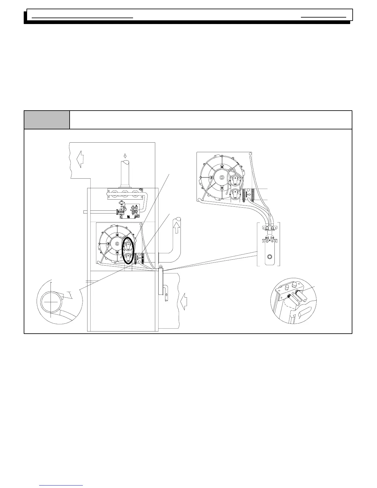
This configuration allows left side venting from the furnace. If right
side venting is required, the combustion blower must be relocated
on the plastic transition box. Remove the four(4) screws that secure
the blower to the transition. Rotate the blower 180° and secure with
the four(4) screws. Use caution to not over tighten the screws to pre-
vent stripping out of the plastic mounting holes.
NOTE: For right side venting, the vent fitting MUST be installed with
the airflow marking arrow pointed toward the vent pipe, with the
drain stub at a 5° to 10° downward slope. (See Figure 44)
Plug the upper drain stub on the vent fitting with the yellow plastic
cap.
For left side mounted condensate trap, connect the
3
/
4
² OD rubber
hose with the 90° bend to the large drain stub on the condensate
trap and secure with a
3
/
4
² clamp.
Route the hose to the drain stub on the bottom of the plastic transi-
tion box. Cut off excess hose and discard. Connect the hose to the
drain stub on the transition and secure with a
3
/
4
² clamp.
For right side mounted condensate trap, connect the
3
/
4
² OD rubber
hose with the 90° bend to the bottom of the plastic transition box and
secure with a
3
/
4
² clamp.
Route the hose to the large drain stub on the condensate pump. Cut
off excess hose and discard. Connect the hose to the drain stub on
the condensate trap and secure with a
3
/
4
² clamp.
Figure 44
Exhaust
Inlet
Supply Air
Return
Air
RIGHT Side Venting
Vent
Drain
Some Models
have one
pressure switch
DRAIN SIDE VIEW
25--24--00
Preassemble
and insert
into furnace
Trap Connection
“Clamp ears”
Pointed O UT
NOTE: TRAP MUST BE PRIMED BEFORE OPERATION
oo
Rotate downward
5°
°°
° to 10°
°°
°
Upflow Installation s (Dual Certified *9MPT & *9MPV--A2 Models)
For left or right side mounted condensate trap, the pressure tap
on the condensate trap MUST be connected to the unused pres-
sure tap located on the upper right hand corner of the plastic transi-
tion box. Remove the plastic caps from the pressure taps on the
condensate trap and the plastic transition and connect with the
5
/
16
²
OD rubber hose. (See Figure 43 and Figure 44)
Connect the
5
/
8
² OD rubber hose with the 90° bend to the lower
drain stub on the vent fitting and secure with a
5
/
8
² clamp.
Route the hose to the small drain stub on the condensate trap. Cut
off excess hose and discard. Connect the hose to the drain stub on
the trap and secure with a
5
/
8
² clamp.
NOTE: Ensure hoses maintain a downward slope to the conden-
sate trap with no kinking or binding for proper condensate drainage.