Two- Stage Multi Position Furnace
Service
Manual
6
440 08 2002 02
Fire or explosion hazard.
Turn OFF gas at shut off before connecting
manometer.
Failure to turn OFF gas at shut off before
connecting manometer can result in death,
personal injury and/or property damage.
!
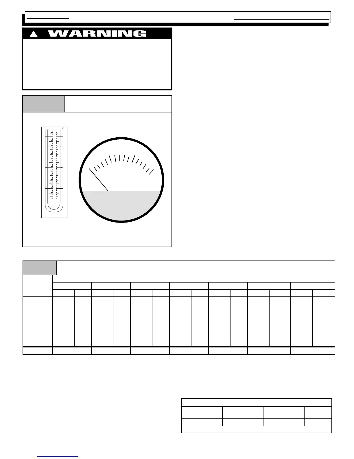
Gas Pressure Testing DevicesFigure 5
MAGNEHELIC
MAX. PRESSURE 15 PSIG
0
510
15
INCHES OF WATER
Pressure Connections
Typical "U" Tube
Manometer
0
1
1
2
2
3
3
CHECKING MANIFOLD PRESSURE
1. Connect manometer or Magnehelic gauge to the
tapped opening on the outlet side of gas valve. Use a
manometer witha0to12² minimum water column
range.
2. T urn gas ON. Operate the furnace on high fire by using
a jumper wire on the R to W1 & W2 thermostat connec-
tions on the fan board.
3. Remove the adjustment cover on the gas valve. Turn
adjusting screw counterclockwise to decrease the
manifold pressure and clockwise to increase. See
Figure 4.
4. Set the manifold pressure to value shown in Table 1 or
Table 2.
5. Operate the furnace on low fire by using a jumper wire
on the R to W1 thermostat connections on the fan
board.
Note: The fourth (4th) DIP switch should be in the on
position to set the low fire manifold pressure. (See wir-
ing digram)
6. Repeat steps 4 and 5 for low fire operation.
7. When the manifold pressures are properly set, replace
the adjustment screw covers on the gas valve.
8. Remove the jumper wires from the thermostat connec-
tions on the fan board. Remove manometer and re-
place plug in gas valve.
9. Reture fourth (4th) DIP switch to previous setting.
10. Replace the burner compartment door.
MANIFOLD PRESSURE AND ORIFICE SIZE FOR HIGH ALTITUDE APPLICATIONS
Table 2
High Altitude Pressure Chart
2000--8000 ft. (Natural Gas)
Elevation Above Sea Level
Heat
alue
0--1999 2000--2999 3000--3999 4000--4999 5000--5999 6000--6999 7000--7999
.
.
High Low High Low High Low High Low High Low High Low High Low
800 3.5 1.7 3.5 1.7 3.5 1.7 3.5 1.7 3.5 1.7 3.5 1.7 3.5 1.7
850 3.5 1.7 3.5 1.7 3.5 1.7 3.5 1.7 3.5 1.7 3.5 1.7 3.5 1.7
900 3.5 1.7 3.5 1.7 3.5 1.7 3.5 1.7 3.5 1.7 3.5 1.7 3.4 1.7
950 3.5 1.7 3.5 1.7 3.5 1.7 3.5 1.7 3.3 1.6 3.2 1.6 3.1 1.5
1000 3.5 1.7 3.4 1.7 3.3 1.6 3.2 1.5 3.0 1.5 2.9 1.4 2.8 1.4
1050 3.2 1.6 3.1 1.5 3.0 1.5 2.9 1.4 2.7 1.3 2.6 1.3 2.5 1.2
1100 2.9 1.4 2.8 1.4 2.7 1.3 2.6 1.3 2.5 1.2 2.4 1.2 2.3 1.1
Orifice Size #42 #42 #42 #42 #42 #42 #42
“CLOCKING” GAS METER (NATURAL GAS)
1. Check with gas supplier to obtain ACTUAL BTU con-
tent of gas.
2. T urn “OFF” gas supply to ALL other gas appliances.
3. Operate furnace on HIGH fire, and time how many se-
conds it takes the smallest (normally 1 cfh) dial on the
gas meter to make one complete revolution.
4. Calculate HIGH fire input rate by using ACTUAL BTU
content of gas in formula shown in example.
5. Operate furnace on LOW fire, and time how many se-
conds it takes the smallest (normally 1 cfh) dial on the
gas meter to make one complete revolution.
6. Calculate LOW fire input rate by using ACTUAL BTU
content of gas in formula shown in example.
Example
Natural Gas
BTU Content
No. of Seconds
Per Hour
Time Per Cubic
Foot in Seconds
BTU Per
Hour
1,000 3,600 48 75,000
1,000 x 3,600 ¸ 48 = 75,000 BTUH