Single Stage Multi Position Furnace
Service
Manual
8
440 08 2001 02
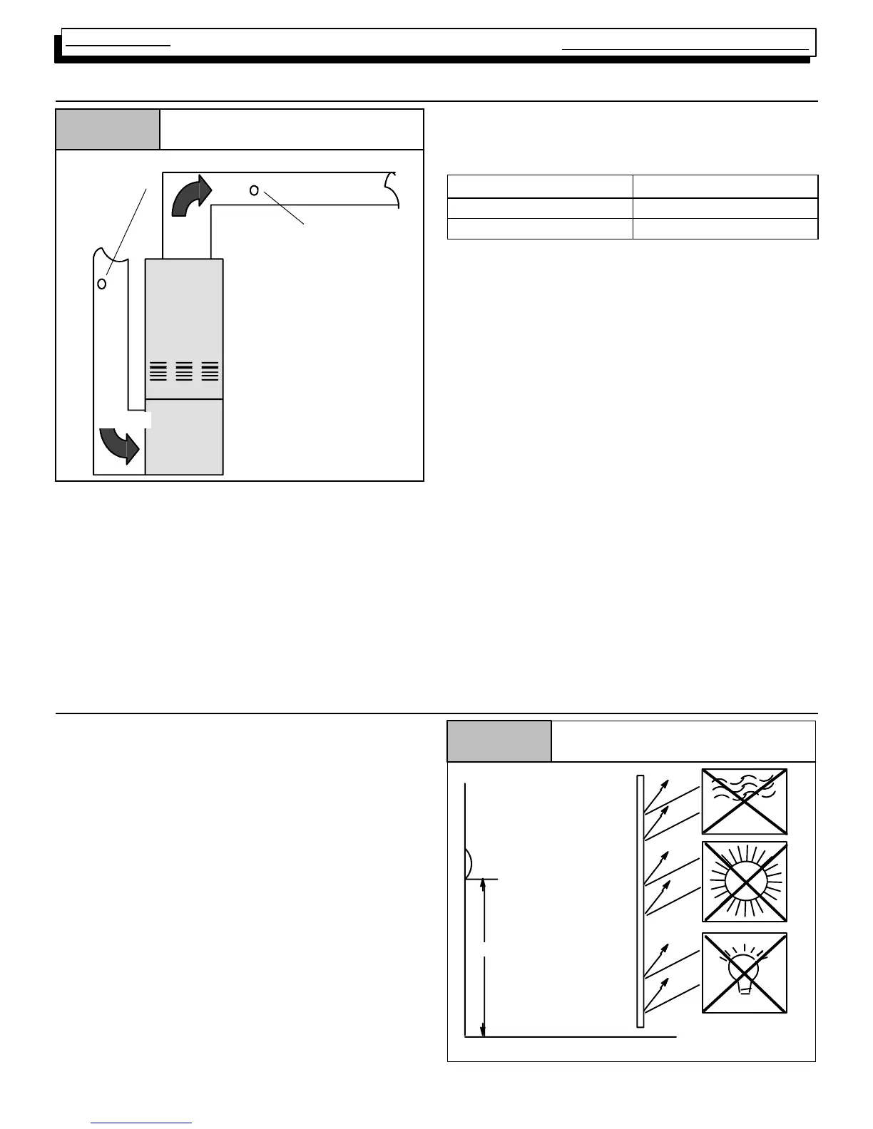
10. CHECKING TEMPERAT URE RISE
Checking Temperature Rise
Figure 8
Thermometer:
Return Air Temp.
Thermometer;
Supply Air Temp.
Supply
Air Flow
Air Flow
Return
The furnace is designed to operate within a certain specified
range of temperature rise.
Operating the furnace outside the specified range may result
in lower efficiency and/or comfort levels, as well as prema-
ture combustion component failures.
Simply stated, the temperature rise through the furnace is
the difference in temperature between the return air, and the
supply air.
NOTE: BEFORE CHECKING TEMPERATURE RISE BE
CERTAIN THAT MANIFOLD PRESSURE I S PROPERLY
ADJUSTED.
ALLOWABLE TEMPERATURE RISE ALL
MODELS
Model
Range
50 Mbtu 35°F--65°F
75, 100 & 125 Mbtu 40°F--70°F
Operate the furnace for 15 minutes before taking tempera-
ture readings. Subtract the return air temperature from the
supply air temperature. The result is the temperature rise.
Compare with the allowable rise listed for the model (size)
you are checking.
Temperature Rise can be checked by placing a thermometer
in the return air duct within 6¢ of furnace. Place a second ther-
mometer in the supply duct at lease two (2) ft. away from the
furnace. (This will prevent any false readings caused by radi-
ation from the furnace heat exchanger) Make sure that the
FILTER IS CLEAN and that ALL REGISTERS AND/OR
DAMPERS ARE OPEN.
If the rise is not within the specified range, it will be necessary
to change the heating blower speed. If the rise is too high,
it will be necessary to increase the blower speed. If the
rise is too low, it will be necessary to reduce the blower
speed.
Example:
Supply Temp. 170
°
Return Temp. 70°
Temperature Rise 100° =
Too High
Solution: Increase Blower Speed
11. R OOM THERMOSTATS
Room thermostats are available from several different
manufactures in a wide variety of styles. They range from the
very simple and inexpensive Bi--metallic type to the complex.
They are simply a switch (or series of switches) designed to
turn equipment (or components) “ON” or “OFF” at the de-
sired conditions.
An improperly operating, or poorly located room thermostat
can be the source of perceived equipment problems. A care-
ful check of the thermostat and wiring must be made then to
insure that it is not the source of problems.
Thermostat Location
Figure 9
5 ft.
DRAFTS
SUN
THERMOSTAT
LIGHT
SHIELD