Single Stage Multi Position Furnace
Service
Manual
12
440 08 2001 02
15. PRESSURE SWITCHES
Transition Pressure Switch
This switch is designed to monitor a blockage of the conden-
sate drain line. It uses a single tap (port) “Normally Open”
pressure switch (wired in series with the furnace air proving
(pressure) switch. The switch “Closes” at a (negative) pres-
sure setting for the switch associated with that particular
model furnace (See unit specitications).
Under normal operating conditions, sufficient pressure is de-
veloped by the exhaust (combustion) blower to close the
switch, and permit the burner to operate. As the condensate
drain begins to back--up, however, the pressure begins to re-
duce. When the pressure drops sufficiently, burner operation
will be prevented until the condition is corrected.
Blower Pressure Switch
An air proving switch (pressure switch) is used on all models
to insure that a draft has been established through the heat
exchanger before allowing burner operation.
To insure continued SAFE, RELIABLE, operation, NEVER
SUBSTITUTE a pressure switch with one that is similar in
appearance. ONLY FACTORY PROVIDED or
AUTHORIZED SUBSTITUTES ARE ACCEPTABLE.
All models installed at altitudes of 4,000¢ above sea level or
higher require replacing the standard pressure switch with a
high altitude pressure switch. The different pressure switch
settings allow continued SAFE, RELIABLE, high altitude
operation.
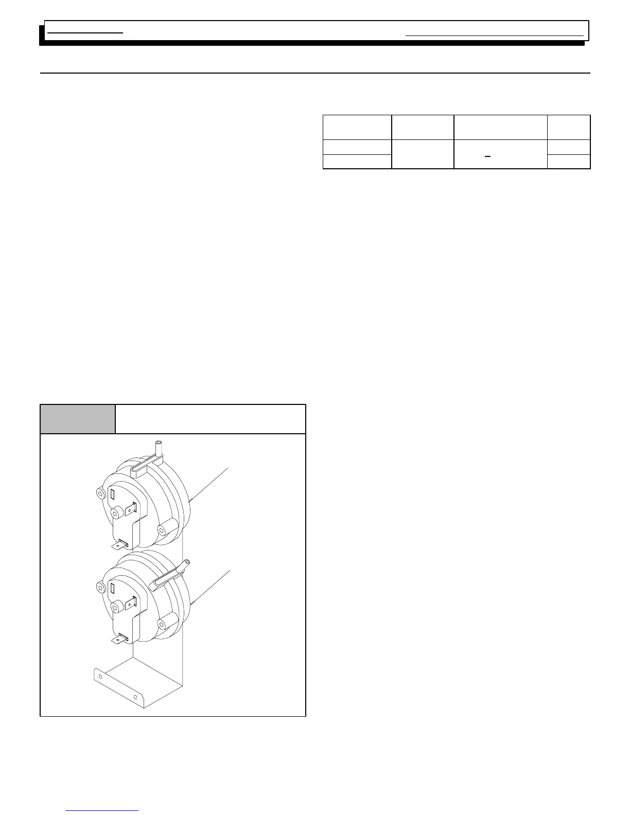
Pressure Switches
Figure 13
25--23--72
T ransition
Blower
HIGH ALTITUDE PRESSURE SWITCHES - ALL
MODELS
Model
Max.
Close
Open Part #
Upflow
²
--
²
Downflow
--1.40
.
.
--
.
.
.
.
--
CHECK CURRENT TECHNICAL SUPPORT MANUAL
FOR PART NOS.
Under normal operating conditions, sufficient negative pres-
sure will be created to close the pressure switch, and keep
it closed to keep furnace operating. Under abnormal condi-
tions, however, such as a restricted vent pipe, or a leak in one
of the heat exchangers, sufficient negative pressure will not
be created. This will result in the switch failing to close or fail-
ing to remain closed during furnace operation.
When servicing a unit whose pressure switch will not close,
or remain closed during operation, the operating pressure of
that furnace should be checked and compared to
approximate operating pressures listed in Table 3 and the
switch setting(s) listed above for the model family you are
servicing.
It is important to remember, that greater negative pressures
are created by the furnace when “HOT” (I.E. upon initial
start--up) than when “COLD” (I.E. after furnaces has been in
operation for a few minutes). Because of this, furnace pres-
sure should ONLY be checked when “HOT” to insure accu-
rate readings.
Table 3 lists approximate operating pressures for Direct
Vent (I.E. Two Pipe) installations of models in this series.
They were obtained in a test lab, under controlled conditions
using two (2) specific vent lengths. They are included in this
manual to provide you with a “Barometer” to gauge our pres-
sures against. The pressures you obtain in the field will differ
slightly from these figures based upon vent length, gas pres-
sure, operating temperature, etc.
Major discrepancies in pressures, will normally cause
problems with pressure switch operation. These Major dis-
crepancies should be investigated as follows: