Single Stage Multi Position Furnace
Service
Manual
13
440 08 2001 02
Table 3 APPROXIMATE OPERATING PRESSURES (²
²²
² OF W.C.)
Model Vent Length @Blower @ Transition
Short -- (5¢ No. Elbows) --1.80 --2.60
5
tu
Long -- (40¢ +590° Elbows) --1.30 --2.30
Short -- (5¢ No. Elbows) --1.80 --2.60
75
tu
Long -- (40¢ +590° Elbows) --1.30 --2.30
Short -- (5¢ No. Elbows) --1.80 --2.60
tu
Long -- (40¢ +590° Elbows) --1.70 --2.50
Short -- (5¢ No. Elbows) --1.80 --2.60
5
tu
Long -- (40¢ +590° Elbows) --1.70 --2.50
Lower (Lesser) Negative Pressures
Lower than normal negative pressures measured at the
Combustion Blower may be caused by:
1. Restriction on the Outlet side of the combustion blow-
er. (I.E. Blocked Flue, Vent too long, Heat Exchanger
leak, etc.)
2. Leak (lack of restriction) on the Inlet side of the com-
bustion blower.
Higher (Greater) Negative Pressures
Higher than normal negative pressures measured at the
Combustion Blower may be caused by:
1. Restriction on the Inlet side of the combustion blower.
(I.E. Plugged Heat Exchanger, air inlet orifice too
small)
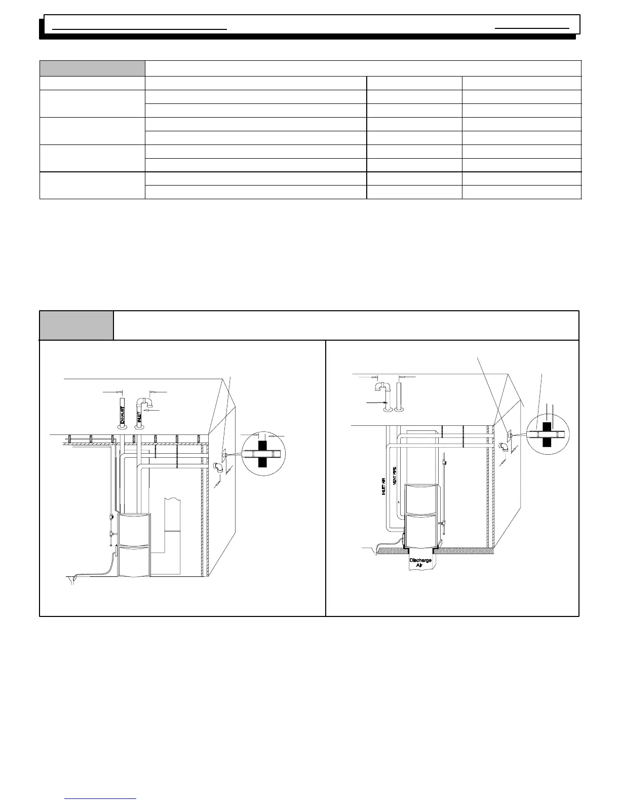
Inlet Pipe
(not used on
Single Pipe
models)
Vent Pipes MUST be
supported Horizontal-
ly and Vertically
*8²
²²
² Min.
20¢
¢¢
¢ Max.
in same
atmospheric zone
Figure 14
*8²
²²
² Min.
20¢
¢¢
¢ Max.
in same atmospheric zone
Coupling on ends of ex-
haust pipe. Total pipe &
coupling outside struc-
ture = 8²
²²
²
Typical Vent/Combustion Air Piping Installation
Aluminum or non--rusting shield recommended.
(See Vent Termination Shielding for dimensions).
* Increase minimum from 8²
²²
² to 18²
²²
² for cold climates (sustained temperatures below
0 °
°°
° F).
DISCHARGE AIR
25--23--33
Inlet Pipe
(not used
on
Single Pipe
models)
UPFLOW
*8²
²²
² Min.
20¢
¢¢
¢ Max.
in same
atmospheric
zone
Vent Pipes MUST
be supported
Horizontally and
Vertically
* Increase minimum from 8²
²²
² to 18²
²²
² for cold climates (sustained temperatures
below 0°
°°
°F).
See Vent Termination Shielding
in Vent Section.
*8²
²²
² Min.
20¢
¢¢
¢ Max.
in same
atmospheric zone
8² Min.
Coupling on inside
and outside of wall to
restrain vent pipe
25--23--33a
DOWNFLOW