Single Stage Multi Position Furnace
Service
Manual
49
440 08 2001 02
SV9541M ELECTRICAL VARIATION
SINGLE STAG E
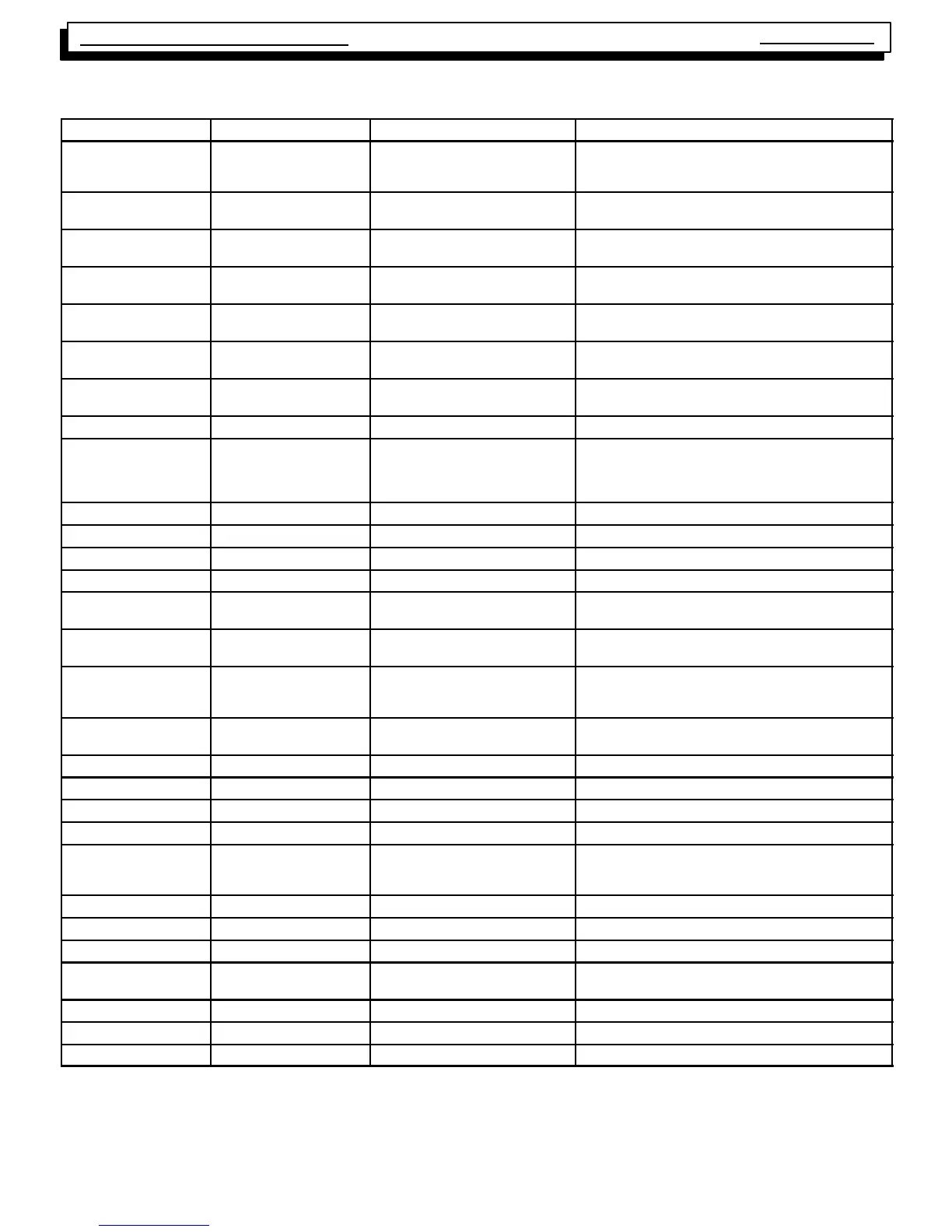
Connector (Pin #) Description Voltage Signal When Signal is Present
Neutrals
(5--
1
/
4
² QC’s)
Neutral 0VAC
(Neutral and earth ground should
be at the same potential)
Always present
L1
(2--
1
/
4
² QC’s)
Line Voltage 115 VAC Present when blower door interlock switch is closed.
HEAT
(
1
/
4
² QC’s)
Fan power *115 VAC Present when Heat fan speed is on (Open Limit mode)
COOL
(
1
/
4
² QC’s)
Fan power *115 VAC Present when Cool fan speed is on (Cool (Y) mode).
EAC
(
1
/
4
² QC’s)
Electronic Air--
Cleaner power
115 VAC Present when High Heat or Cool fan speed is on.
CONSTANT FAN
(
1
/
4
² QC’s)
Continuous Fan
power
*115 VAC Present when other fan speeds is off.
HUM
(
1
/
4
² QC’s)
Humidifier power 115 VAC Present when the Heat speeds is on.
P1 (pin 1) Line Voltage 115 VAC Present when the door interlock switch is closed.
P1 (pin 2) Data Line Non--periodic
1
/2
wave rectified AC
(measures as an unstable AC volt-
age bouncing between 12 V AC and
16 VAC
Present when the door interlock switch is closed.
P1 (pin 3) C (xfmr common) 0VAC Always present
P1 (pin 4) Neutral 0VAC Always present
P1 (pin 5) 24 VAC 24 VAC Present when the door interlock switch is closed.
P1 (pin 6) R 24 VAC Present when the door interlock switch is closed.
C1 (pin 1) Limit return
1
/2
wave rectified AC Present when the door interlock switch is closed. This
voltage decreases when a limit switch is open.
C1 (pin 2) Pressure Switch supply
1
/2
wave rectified AC Present when the door interlock switch is closed. This
signal is the same as the C1 (pin 1)
C1 (pin 3) Pressure Switch return
1
/2
wave rectified AC Present when the door interlock switch is closed. This
AC voltage decreases when the Low Pressure Switch
closes.
C1 (pin 4) Data Line Non--periodic
1
/2
wave
rectified AC
Present when the door interlock switch is closed. Same
signal as P1 (pin 5).
C1 (pin 5) Limit Supply
1
/2
wave rectified AC Present when the 24 VAC transformer is powered.
C1 (pin 6) C (xfmr common) 0VAC Always present
C1 (pin 7) R 24 VAC Present when the door interlock switch is closed.
C1 (pin 8) 24 V AC 24 VAC Present when the door interlock switch is closed.
C2 (pin 1) HSI return 24 VAC (with igniter present) Present when HSI is not turned on. When HSI is on, this
signal is 0 VAC to 10 VAC depending on input line volt-
age potential.
C2 (pin 2) HSI supply 24 VAC Present when the door interlock switch is closed.
C2 (pin 3) Not connected 0VAC Not connected
C2 (pin 4) Flame sense >80 VAC Present when the door interlock switch is closed.
C3 (pin 1) Inducer supply 115 VAC Present when the inducer draft blower motor is on (Heat
modes, Open Limit mode).
C3 (pin 2) L1 115 VAC Present when the door interlock switch is closed.
C3 (pin 3) Inducer return 0VAC Always present (neutral connection).
C3 (pin 4) L2 (neutral) 0VAC Always present
* With a motor tap connected, voltage appears at “unpowered” fan terminals whenever the motor is running due to feedback through the motor windings.
** Voltage appears on the “unpowered” inducer terminal whenever the inducer motor is running due to feedback through the motor windings.
NOTE1: Using a Fluke 79 digital Multi--Meter (DMM),
1
/2
wave rectified AC voltage typically measures about 14 VAC. The Fluke 79 is not a “true” RMS
meter .