Single Stage Multi Position Furnace
Service
Manual
10
440 08 2001 02
The COOLING fan speed is energized via the “Y” terminal.
Failure to connect the thermostat “Y” terminal to the “Y” ter-
minal on the control will result in the failure to energize the
COOLING speed on a call for cooling from the thermostat.
(The HEATING speed will be energized instead via the “G”
terminal)
13. TWINNING KITS
Some installations may require a Heating capacity or Airflow
capabilities greater than a single furnace of this series can
provide.. When this is necessary, furnaces may be installed
in a “T winned” configuration.
The Twinning Kit allows the two (2) furnaces to be controlled
by the same room thermostat. When Twinned, the circulat-
ing (conditioned air) blowers of BOTH furnaces will operate
simultaneously.
Models equipped with a HONEYWELL ST9160B series Fan
T imer/Furnace Control may be twinned using a model
NAHA003WK01 twinning kit.
To assist troubleshooting efforts of “Twinned” installations,
“TYPICAL” control wiring diagrams are provided on pages **
through **.
14. LIMIT SWITCHES
T wo (2) dif ferent kinds of limit switches are used on this se-
ries of furnaces. They are the main limit and roll out limit
switches. The main limit, and roll limit switches are used on
all models.
NOTE: All limit switches are safety devices and other
than for testing purposes, should never be jumped out!
Limit switches are “normally closed” electrical switches, de-
signed to open when their predetermined “limit setting” has
been reached.
It should also be remembered, that when a limit switch
opens, it more than likely is not due to a bad switch! The
cause of the opening limit must be found and corrected, be-
fore the furnace can resume proper operation.
Fire hazard.
Limit controls are factory preset and MUST NOT be
adjusted. Use ONLY manufacturer’ s authorized
replacement parts.
Failure to do so can result in death, personal injury
and/or property damage.
!
The specific functions of the two (2) limit switches used in
this series of furnaces are as follows:
MAIN LIMIT SWITCH
A “Normally Closed” switch located on the front partition of
the furnace. It monitors supply air temperature, and inter-
rupts furnace (burner) operation when a supply air tempera-
ture is sensed which would result in the furnace exceeding
Maximum allowable outlet air temperature. While the main
limit is open, combustion blower, and/or the circulating blow-
er will be energized continuously. This control is an “Auto-
matic” reset control, which will reset itself when the tempera-
ture sensed drops to a safe level.
If furnace (burner) cycles on this limit switch, (I.E. switch
opens and closes during furnace operation) it is more than
likely due to a high temperature rise through the furnace.
(See checking temperature on page 8 of this manual)
High temperature rise can be caused by either OVER
FIRING (high manifold pressure. incorrect orifices, etc.) or
LOW AIR FLOW (dirty filter, blower speed too low, excessive
static in duct system, etc.)
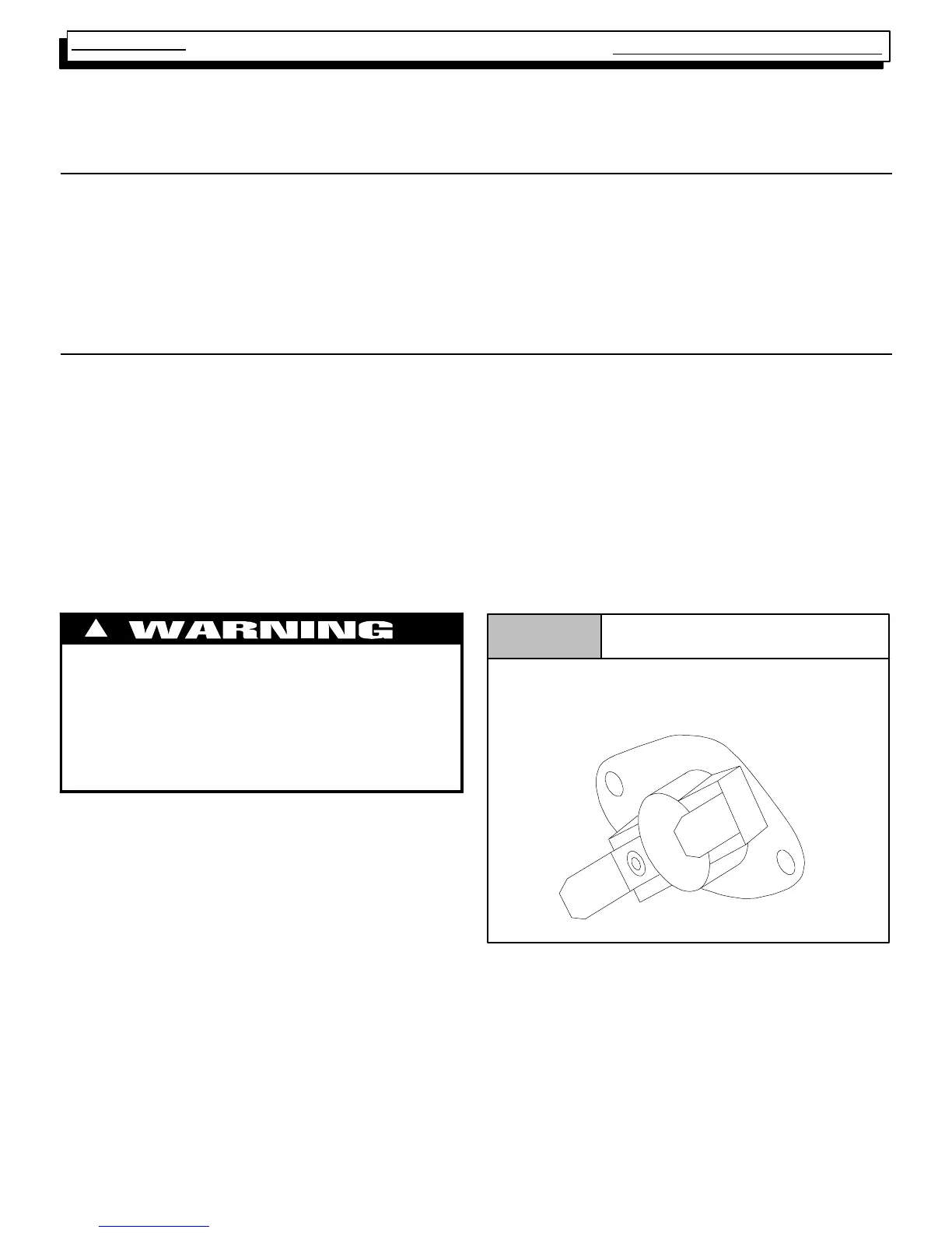
Typical Limit Switch
Figure 11