Single Stage Multi Position Furnace
Service
Manual
16
440 08 2001 02
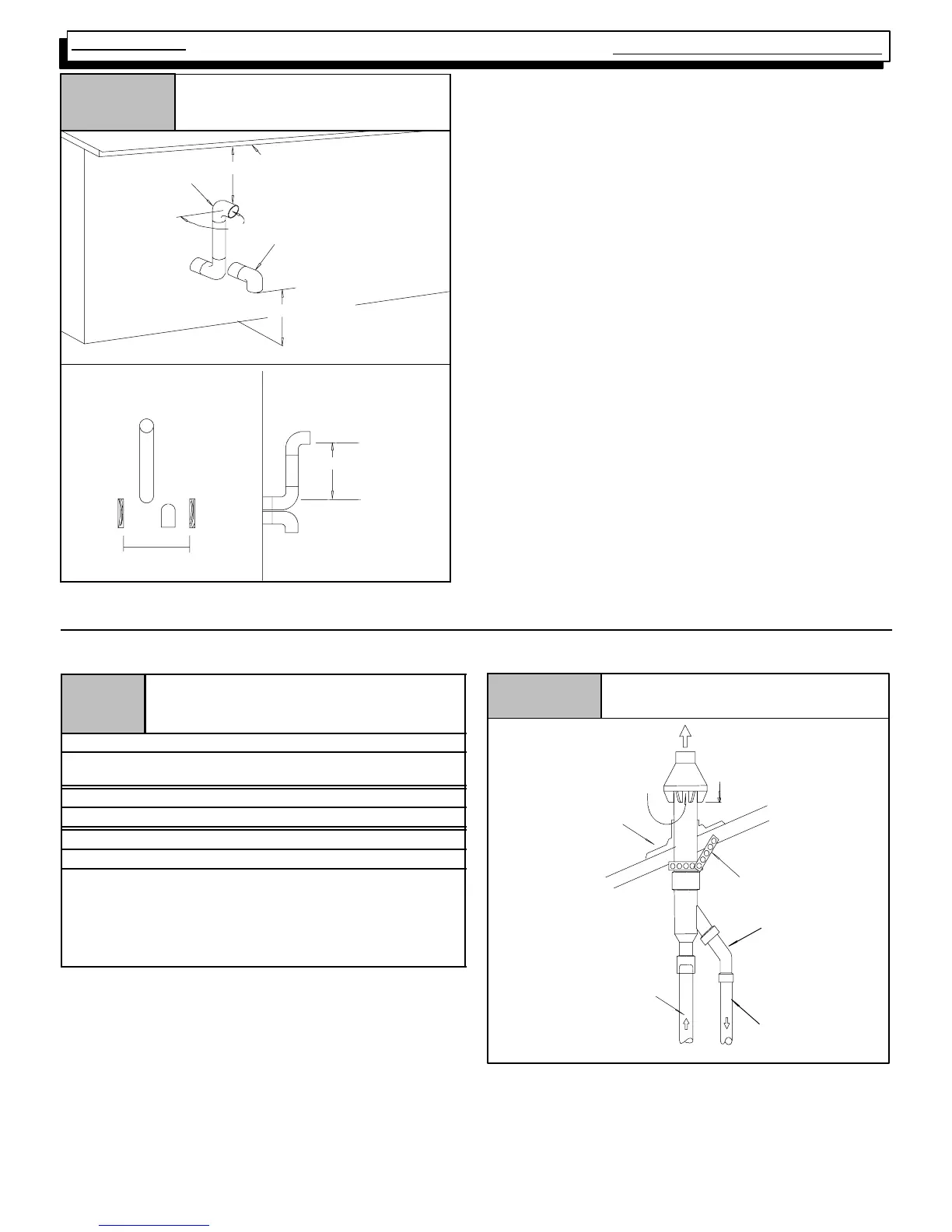
Figure 22
Recommended Alternate Installa-
tion for Sustained Cold Weather
(--0°
°°
° F & below)
OVERHANG
12²
²²
² MIN.
12² MIN. Ground
Level
OR Snow Level
INLET
EXHAUST
90°
°°
°
Same Joist
Space
FRONT VIEW
SIDE VIEW
25--23--73
12²
18. CONCENTRIC VENT TERMINATION
Vent/Combustion Air Piping Charts
Table 6
Concentric Termination Kit NAHA001CV
& NAHA002VC Venting Table Dual Piping
ONLY
50,000 & 75,000 Btuh Furnaces
NAHA002CV -- 35¢ & (4) 90° elbows with 2² PVC pipe
NAHA001CV -- 65¢ & (4) 90° elbows with 3² PVC pipe
100,000 Btuh Furnace
NAHA001CV -- 65¢ & (4) 90° elbows with 3² PVC pipe
125,000 Btuh Furnace
NAHA001CV -- 35¢ & (4) 90° elbows with 3² PVC pipe
1. Do not include the field supplied 45° elbow in the total
elbow count.
2. If more than four elbows are required, reduce the length of
both the inlet and the exhaust pipes five feet for each
additional elbow used.
3. Elbows are DWV long radius type for 2² and 3² vents.
Concentric Vent Roof Installation
Figure 23
Maintain 12² min. clearance
above highest anticipated
snow level. Max. of 24² above
roof.
Combustion Air
Roof Boot/
Flashing
(Field Supplied)
Combustion
Air
Vent
Vent
Support
(Field Supplied)
45° Elbow
(Field Supplied)
25--22--02
Note:
Support must be field installed to secure termination kit to structure.