Single Stage Multi Position Furnace
Service
Manual
22
440 08 2001 02
28. BLOWER ASSEMBLY
All models use a multi--speed, permanent split capacitor mo-
tor, direct--drive, blower assembly. Different size (HP) mo-
tors and/or different diameter blower wheels are used in
each model to obtain the required air flow. The entire blower
assembly slides out on rails for servicing after removing the
two screws at the front.
SELECTING BLOWER SPEEDS
The wide variety of applications and installations of furnaces
throughout the country makes it impossible to “Factory Se-
lect” blower speeds that will provide proper operation for all
installations. This means then, that the blower speeds for
both heating and cooling must be “Field Selected” for each
particular installation to insure proper operation. is to prevent
wide swings in room temperature during furnace operation.
The criteria for selecting the proper blower speeds IS NOT
“High for Cooling, Low for Heating”. Although that may be
how it works out SOMETIMES, it can (in many cases) be ex-
actly the opposite. (I.E. a Lower speed for Cooling, and a
Higher speed for Heating)
The PROPER CRITERIA FOR SELECTING BLOWER
SPEEDS is as follows:
HEATING
A blower speed must be selected that will provide proper
temperature rise through the furnace. (See “checking tem-
perature rise” found elsewhere in this manual), The required
CFM for a particular temperature rise can also be calculated
using the following formula:
Output BTU
Temp. Rise X 1.08 = CFM
EXAMPLE: using a 75 Mbtu furnace of this series with an
output of 67,500 Btuh and a desired temperature rise of 50°
F (range of 40--70° F allowable) and a measured external
static pressure of 0.2² W.C. with a dry coil.
67,500
or 67,500
50 X 1.08 54 = 1250 CFM
Checking the blower performance data for this model, (see
Figure 36) indicates that @ 0.2² W.C. E.S.P. medium--high
speed will deliver 1249 CFM. Accordingly, medium speed
should be used in this example for the HEATING speed.
COOLING
A blower speed must be selected that will provide proper air
flow (Nominal 400 CFM per ton) for the size (capacity) air
conditioning coil being used at the external static pressure
of the Duct system (installation). This requires CHECKING
THE EXTERNAL STATIC PRESSURE, then consulting the
BLOWER PERFORMANCE DATA to determine the re-
quired speed tap.
EXAMPLE: A 24,000 BTU (2 TON) air conditioning system,
using the same 75,000 BTU furnace as in the previous ex-
ample. The external static pressure is measured and found
to be 0.4² W.C.
400 CFM (nominal) per TON required
400x2=800CFMrequired
Checking the blower performance data (see Figure 36) for
this model indicates that @ 0.4² W.C. ESP low speed will de-
liver 788 CFM. Accordingly, low speed should be used in this
example for the COOLING speed.
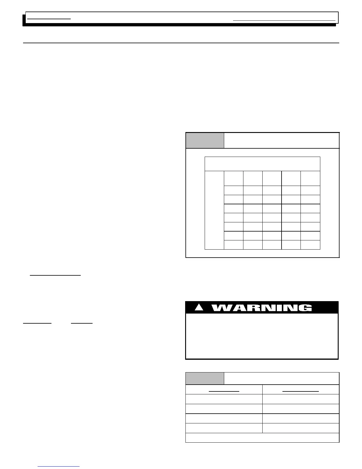
Table 7
Blower Performance Data
75,0000 BTUH
Air Delivery in Cubic Feet per Minute (CFM)
(Furnace Rated @ 0.5² W.C. ESP)
TAP LOW MED
L
MED H HIGH
sure
.10 778 984 1263 1576
Pres
.C.
.20 786 1003 1249 1532
atic
of
.30 790 1003 1244 1489
lSt
hes
.40 788 1001 1215 1432
erna
In
.50 781 982 1186 1371
Ext
.60 765 962 1146 1308
.70 743 923 1094 1229
SAMPLE ONLY
CHANGING BLOWER SPEED
The procedure for changing blower speeds (if needed) is
shoun in Table 8.
Electrical shock hazard.
Turn OFF power to furnace before changing speed
taps.
Failure to do so can result in death and/or personal
injury.
!
Table 8 Blower Speed Chart
Wire Color Motor Speed
Black High
Orange* Med--High
Blue Medium
Red Low
*Med--High speed may not be provided on all models.