Single Stage Multi Position Furnace
Service
Manual
4
440 08 2001 02
6. The Combustion Blower Assembly is mounted on the
outlet side of the Secondary heat exchanger , This
blower creates a partial vacuum (negative pressure)
within the heat exchangers drawing the flue products
out of the furnace.
7. A pressure switch (Air Proving Switch) is used as a
safety device that prevents the ignition system from f ir-
ing the furnace until it senses that a proper draft has
been established through the furnace.
4. ELECTRICAL SUPPLY
Electrical shock hazard.
Turn OFF electric power at fuse box or service panel
before making any electrical connections and en-
sure a proper ground connection is made before
connecting line voltage.
Failure to do so can result in death, personal injury
and/or property damage.
!
SUPPLY CIRCUIT
The furnace cannot be expected to operate correctly unless
it is properly connected (wired) to an adequately sized (15
amp.) single branch circuit.
SUPPLY VOLTAGE
Supply voltage to the furnace should be a nominal 115 volts.
It MUST be between 97 volts and 132 volts. Supply voltage
to the furnace should be checked WITH THE FURNACE IN
OPERATION. Voltage readings outside the specified range
can be expected to cause operating problems. Their cause
MUST be investigated and corrected.
ELECTRICAL GROUND
Grounding of the electrical supply to ALL FURNACES IS
REQUIRED for safety reasons.
CHECKING GROUNDING AND POLARITY
Grounding may be verified as follows:
1. T urn the power supply “OFF”.
2. Using an Ohmmeter check for continuity between the
Neutral (white) wire and Ground wire (green) of the
supply circuit.
3. With the Ohmmeter set on the R x 1 scale, the reading
should be zero Ohms.
4. A zero Ohm reading indicates that the neutral is
grounded back to the main panel.
5. An alternate check would be to check for continuity
from the Neutral to a cold water pipe, (Pipe must be
metal, and must have a continuous, uninterrupted con-
nection to ground) or to a continuous, uninterrupted
connection to ground) or to a driven ground rod.
6. Any readings other than zero Ohms would indicate a
poor ground, or no ground.
Polarity may be verified as follows:
1. T urn the power supply “ON”.
2. Using a Voltmeter check for voltage between the Hot
(Black) and Neutral (White) wire of supply circuit.
POLARITY
CORRECT POLARITY of the line voltage supply to all fur-
naces is also required for safety reasons.
3. Reading should be Line (Supply) Voltage.
4. Check for Voltage between the Neutral (White) wire
and Ground wire of the supply circuit.
5. Reading should be zero Volts. (if line voltage is read,
polarity is reversed)
6. A zero V olt reading indicates there is no voltage poten-
tial on Neutral wire.
7. Double check by checking for voltage between the Hot
(Black) wire and Ground wire of the supply circuit.
8. Reading should be Line (supply) Voltage.(ifzero
volts is read, there is no ground, or polarity is re-
versed.)
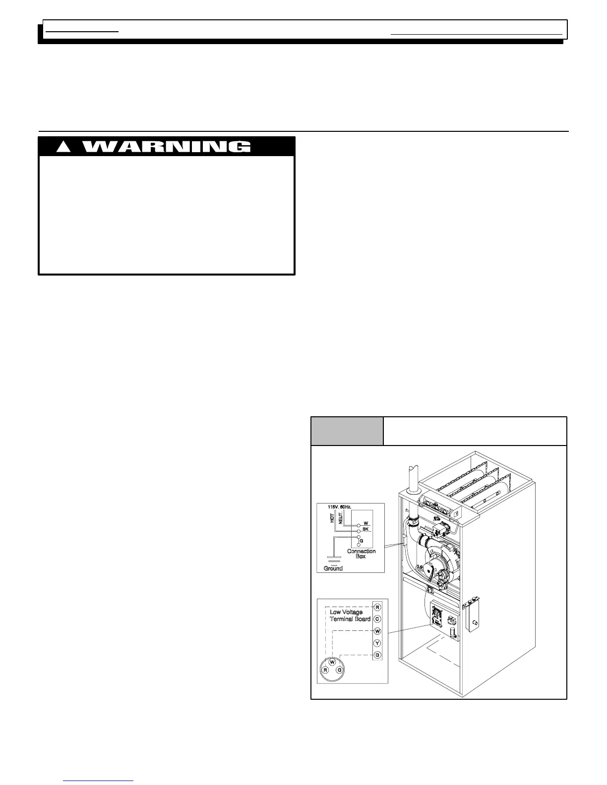
Figure 2
Electrical Conn ectio n s
NOTE: Junction Box can
be mounted to either the
left or right side.
25--23--42