2. A pluggedcondensatedrainlineorafailedcondensate
pumpwillallowcondensateto spill.If thefurnaceis
installedwhereacondensatespillcouldcausedamage,it
isrecommendedthatanauxiliarysafetyswitchbeinstalled
topreventoperationoftheequipmentintheeventofpump
failureorpluggeddrainline.Ifused,anauxiliarysafety
switchshouldbeinstalledintheRcircuit(lowvoltage)
ONLY.
CondensateDrainTrap FreezeProtection
Special precautions MUST be made if installing furnace in an
area which may drop below freezing. This can cause improper op-
eration or damage to the equipment. If the the furnace environ-
ment has the potential of freezing, the drain trap and drain line
must be protected. Use 3 to 6 watt per foot at 115 volt, 40 ° F self-
regulating shielded and waterproof heat tape. Wrap the drain trap
and drain line with the heat tape and secure with the ties. Follow
the heat tape manufacturer's recommendations.
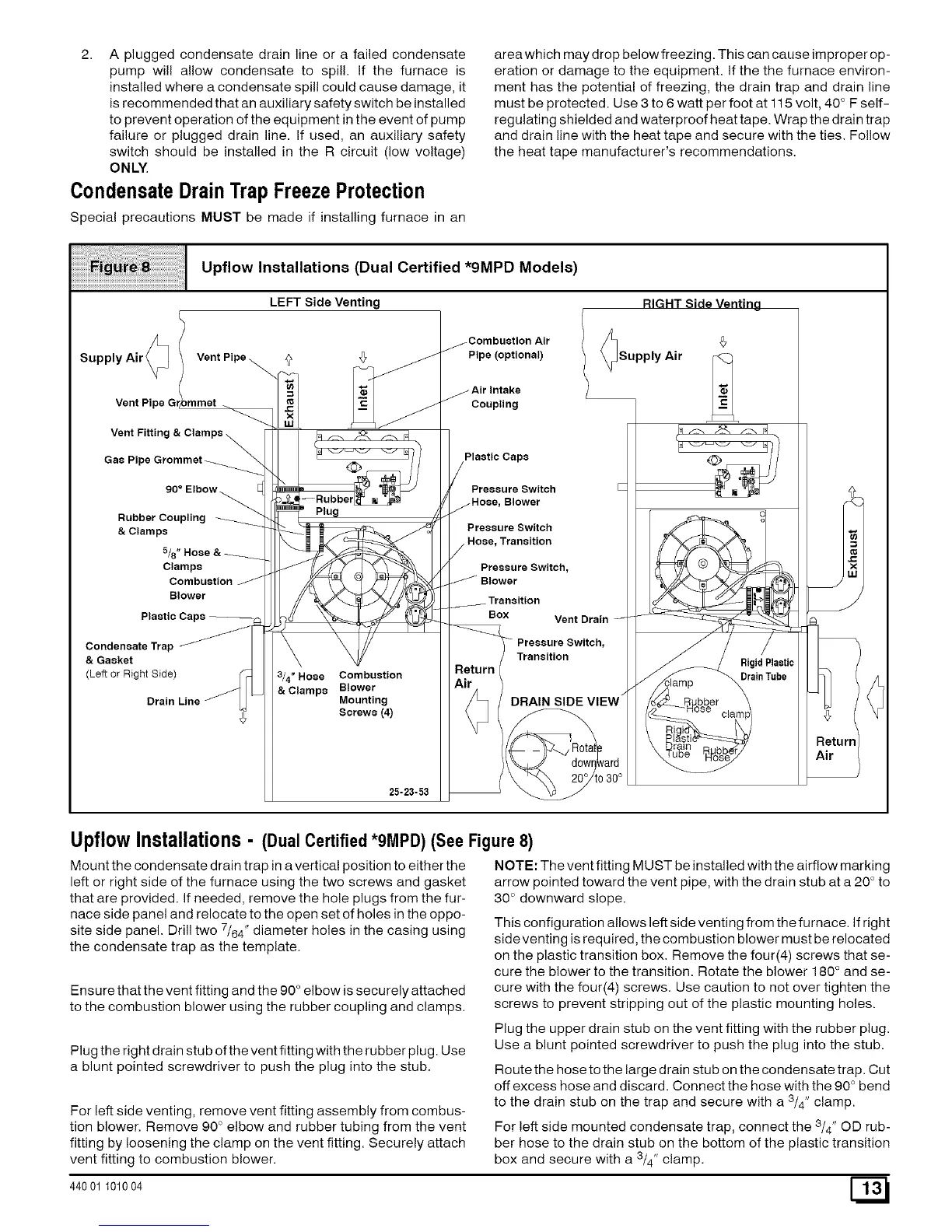
Upflow Installations (Dual Certified *9MPD Models)
LEFT Side Venting
Supply Air _ Vent Pipe
Vent Pipe
Vent Fittin,
Gas Pipe
90 ° Elbow
Rubber Coupling
&Clamps
5/8
Clamps
Combustion
Blower
Plastic
CondensateTrap _
& Gasket
(Left or Right Side)
Drain Line
Plug
3/4" Hose Combustion
& Clamps Blower
Mounting
Screws (4)
25-23-53
Pipe (optional)
lSupply Air
Coupling
Plastic Caps
Pressure Switch
Blower
Pressure Switch
Transition
Pressure Switch,
Transition
Box Vent Drain
Pressure Switch,
Transition
DRAIN SIDE VIEW _
:lamp
Rigid Plastic
Drain Tube
UpflowInstallations- (Dual Certified*9MPD) (See Figure8)
Mount the condensate drain trap in a vertical position to either the
left or right side of the furnace using the two screws and gasket
that are provided. If needed, remove the hole plugs from the fur-
nace side panel and relocate to the open set of holes in the oppo-
site side panel. Drill two 7/64" diameter holes in the casing using
the condensate trap as the template.
Ensure that the vent fitting and the 90 ° elbow is securely attached
to the combustion blower using the rubber coupling and clamps.
Plug the right drain stub of the vent fitting with the rubber plug. Use
a blunt pointed screwdriver to push the plug into the stub.
For left side venting, remove vent fitting assembly from combus-
tion blower. Remove 90 ° elbow and rubber tubing from the vent
fitting by loosening the clamp on the vent fitting. Securely attach
vent fitting to combustion blower.
44001 101004
NOTE: The vent fitting MUST be installed with the airflow marking
arrow pointed toward the vent pipe, with the drain stub at a 20 ° to
30 ° downward slope.
This configuration allows left side venting from the furnace. If right
sideventing is required, the combustion blower must be relocated
on the plastic transition box. Remove the four(4) screws that se-
cure the blower to the transition. Rotate the blower 180 ° and se-
cure with the four(4) screws. Use caution to not over tighten the
screws to prevent stripping out of the plastic mounting holes.
Plug the upper drain stub on the vent fitting with the rubber plug.
Use a blunt pointed screwdriver to push the plug into the stub.
Route the hose to the large drain stub on the condensate trap. Cut
off excess hose and discard. Connect the hose with the 90 ° bend
to the drain stub on the trap and secure with a 3/4" clamp.
For left side mounted condensate trap, connect the 3/4" OD rub-
ber hose to the drain stub on the bottom of the plastic transition
box and secure with a 3/4" clamp.
 Loading...