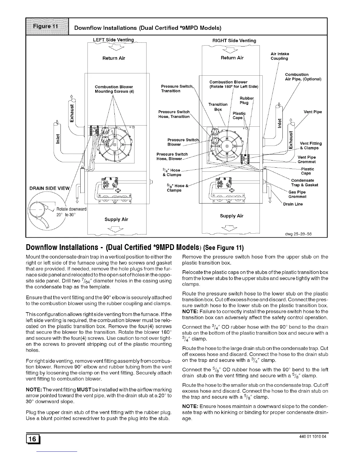
Downflow Installations (Dual Certified *gMPD Models)
LEFT Side Venting_
"4C>
Return Air
Combustion Blower
Mounting Screws (4)
Supply Air
Pressure Switch,
Transition
Pressure Switch
Hose, Transition _
Blower
Pressure Switch
Hose,
3/4
& Clamps
5/8°
Clamps
RIGHT Side Venting
<z>
Return Air
Combustion Blower
0
Transition
Box
Supply Air
Air Intake
Coupling
Combustion
Air Pipe, (Optional)
Vent Pipe
__e_ltFittin g
mps
Vent Pipe
Grommet
Caps
Condensate
Trap & Gasket
pe
Grommet
Drain Line
dwg 25-23-56
Downfl0wInstallations- (DualCertified*9MPDModels)(See Figure 11)
Mount the condensate drain trap in a vertical position to either the
right or left side of the furnace using the two screws and gasket
that are provided. If needed, remove the hole plugs from the fur-
nace side panel and relocated to the open set of holes in the oppo-
site side panel. Drill two 7/64" diameter holes in the casing using
the condensate trap as the template.
Ensure that the vent fitting and the 90 ° elbow is securely attached
to the combustion blower using the rubber coupling and clamps.
This configuration allows right side venting from the furnace. Ifthe
left side venting is required, the combustion blower must be relo-
cated on the plastic transition box. Remove the four(4) screws
that secure the blower to the transition. Rotate the blower 180 °
and secure with the four(4) screws. Use caution to not over tight-
en the screws to prevent stripping out of the plastic mounting
holes.
For right side venting, remove vent fitting assembly from combus-
tion blower. Remove 90° elbow and rubber tubing from the vent
fitting by loosening the clamp on the vent fitting. Securely attach
vent fitting to combustion blower.
NOTE: The vent fitting MUST be installed with the airflow marking
arrow pointed toward the vent pipe, with the drain stub at a 20 ° to
30° downward slope.
Plug the upper drain stub of the vent fitting with the rubber plug.
Use a blunt pointed screwdriver to push the plug into the stub.
Remove the pressure switch hose from the upper stub on the
plastic transition box.
Relocate the plastic caps on the stubs of the plastic transition box
from the lower stubs to the upper stubs and secure tightly with the
clamps.
Route the pressure switch hose to the lower stub on the plastic
transition box. Cut off excess hose and discard. Connect the pres-
sure switch hose to the lower stub on the plastic transition box.
NOTE: Failure to correctly install the pressure switch hose to the
transition box can adversely affect the safety control operation.
Connect the 3/4" OD rubber hose with the 90 ° bend to the drain
stub on the bottom of the plastic transition box and secure with a
3/4" clamp.
Route the hose to the large drain stub on the condensate trap. Cut
off excess hose and discard. Connect the hose to the drain stub
on the trap and secure with a 3/4" clamp.
Connect the 5/8" OD rubber hose with the 90 ° bend to the left
drain stub on the vent fitting and secure with a 5/8" clamp.
Route the hose to the smaller stub on the condensate trap. Cut off
excess hose and discard. Connect the hose to the drain stub on
the trap and secure with a 5/8" clamp.
NOTE: Ensure hoses maintain a downward slope to the conden-
sate trap with no kinking or binding for proper condensate drain-
age.
[_ 440 01 101004
 Loading...