For right side mounted condensate trap, the rigid plastic drain
tube MUST be used, Cut two 2" long sections from the 3/4" OD
rubber hose, Connect the plastic drain tube to the drain stub on
the bottom of the plastic transition box and to the stub on the con-
densate trap using the two hose sections and 3/4" clamps.
Route the hose to the small drain stub on the condensate trap. Cut
off excess hose and discard. Connect the hose to the drain stub
on the trap and secure with a 5/8" clamp.
NOTE: The support leg on the plastic drain tube MUST be posi-
tioned on the blower partition.
Connect the 5/8" OD rubber hose with the 90 ° bend to the left
drain stub on the vent fitting and secure with a 5/8" clamp.
NOTE: Ensure hoses maintain a downward slope to the conden-
sate trap with no kinking or binding for proper condensate drain-
age.
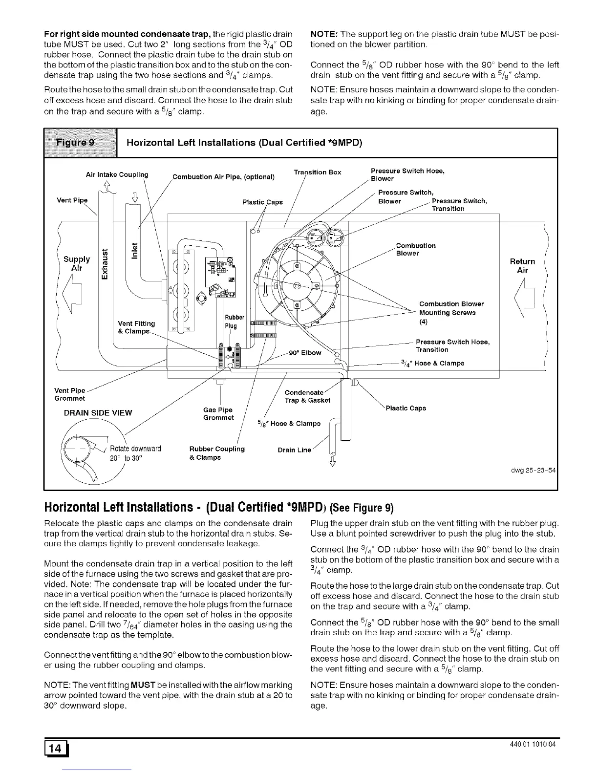
Horizontal Left Installations (Dual Certified *9MPD)
Transition Box
Air Intake Combustion Air Pipe, (optional)
ly =
J_
x
LU
Vent Fitting
Elbow
Preasure Switch Hose,
Blower
Preaaure Switch,
Blower Pressure Switch,
_ Transition
Combustion
Combustion Blower
Mounting Screws
(4)
Transition
3/4" Hose & Clamps
Return
Air
Vent Pipe
Grommet
DRAIN SIDE VIEW
Gas Pipe
Grommet
Trap & Gasket
5/8" Hose & Clamps
Rotatedownward Rubber Coupling
20° to 30° & Clamps
dwg 25-23-54
HorizontalLeftInstallations- (DualCertified*9MPD) (See Figure 9)
Relocate the plastic caps and clamps on the condensate drain
trap from the vertical drain stub to the horizontal drain stubs. Se-
cure the clamps tightly to prevent condensate leakage,
Mount the condensate drain trap in a vertical position to the left
side of the furnace using the two screws and gasket that are pro-
vided. Note: The condensate trap will be located under the fur-
nace in a vertical position when the furnace is placed horizontally
on the left side. If needed, remove the hole plugs from the furnace
side panel and relocate to the open set of holes in the opposite
side panel. Drill two 7/64" diameter holes in the casing using the
condensate trap as the template.
Connect the vent fitting and the 90 ° elbow to the combustion blow-
er using the rubber coupling and clamps.
Plug the upper drain stub on the vent fitting with the rubber plug.
Use a blunt pointed screwdriver to push the plug into the stub.
Connect the 3/4" OD rubber hose with the 90 ° bend to the drain
stub on the bottom of the plastic transition box and secure with a
3/4" clamp.
Route the hose to the large drain stub on the condensate trap. Cut
oft excess hose and discard. Connect the hose to the drain stub
on the trap and secure with a 3/4" clamp.
Connect the 5/8" OD rubber hose with the 90 ° bend to the small
drain stub on the trap and secure with a 5/8" clamp.
Route the hose to the lower drain stub on the vent fitting. Cut oft
excess hose and discard. Connect the hose to the drain stub on
the vent fitting and secure with a 5/8" clamp.
NOTE: The vent fitting MUST be installed with the airflow marking
arrow pointed toward the vent pipe, with the drain stub at a 20 to
30° downward slope.
NOTE: Ensure hoses maintain a downward slope to the conden-
sate trap with no kinking or binding for proper condensate drain-
age.
[_ 440 01 101004
 Loading...