InstallationRequirements
1. Install furnace level.
2. This furnace is NOT to be used for temporary heat of build-
ings or structures under construction.
3. Install furnace as centralized as practical with respect to the
heat distribution system.
4. Install the vent pipes as short as practical. (See Vent and
Combustion Air Piping section).
5. Maintain clearance for fire safety and servicing. A front
clearance of 30" is recommended for access to the burner,
controls and filter.
6. Use a raised base for upflow furnace if the floor is damp or
wet at times.
For downflow installations, non combustible subbase must
be used under the furnace unless installation is on a non
combustible floor surface. This requirement applies even
when a coi! box or cabinet is used.
Fire Hazard.
Place furnace on noncombustible subbase on
downflow applications, unless installing on
non-combustible flooring.
Failure to install unit on noncombustible
subbase can result in death, personal injury
and/or property damage.
9.
For horizontal installations, line contact is permissible only
between lines formed by intersection of back and two sides
of furnace jacket, and building joists, studs or framing.
Residential garage installations require:
Burners and ignition sources installed at least 18" above
the floor.
• Located or physically protected from possible damage
by a vehicle.
10. Local codes may require a drain pan under the entire fur-
nace and condensate trap when the furnace is installed in
attic application.
InstallationPositions
This furnace can be installed in an upflow, horizontal (either left or
right) or downflow airflow position. DO NOT install this furnace on
its back. For the upflow position, the return air ductwork can be
attached to either the left or right side panel and/or the bottom. For
horizontal and downflow positions, the return air ductwork must
be attached to the bottom. The return air ductwork must never be
attached to the back of the furnace.
FurnaceInstallationConsiderations
The installation of the furnace for a given application will dictate
the position of the furnace, the airflow, ductwork connections,
vent and combustion air piping. Consideration must be given to
the following:
CondensateTrap and Drain Lines
The supplied condensate trap must be attached to the furnace
side panel on either the left or right side. For horizontal installa-
tions, the drain trap is vertically attached to the side panel below
the furnace. A minimum clearance of 5" below the furnace is re-
440 01 101004
quired for the condensate trap. Downward slope of the conden-
sate drain line from the condensate trap to the drain location must
be provided. Adequate freeze protection of the drain trap and the
drain line must be provided. See "Condensate Drain Trap"section
for further details.
Leveling
Proper leveling of the furnace must be provided to insure proper
drainage of the condensate from the furnace. The furnace must
be level to within 1/4" from front to back and from side to side for
upflow and downflow installations or top to bottom for horizontal
installations.
Vent and Combustion Air Connections
On the Dual Certified furnace, the vent and combustion air pipes
attach to the furnace through the top panel for the upflow and hori-
zontal installations. For the downflow installation, the vent and
combustion air pipes attach to the furnace through the alternate
locations on the furnace side panels.
Note: On the Direct Vent furnace, the vent pipe attaches to the fur-
nace through the side panels. The combustion air pipe attaches to
the top panel or to the alternate location on the side panel.
On the Single Pipe furnace, the vent pipe attaches to the furnace
through the furnace side panels.
Note: Repositioning of the combustion blower is required for the
vent pipe connection to the furnace through the "right side" panel.
See "Vent and Combustion Air Piping" section for further details.
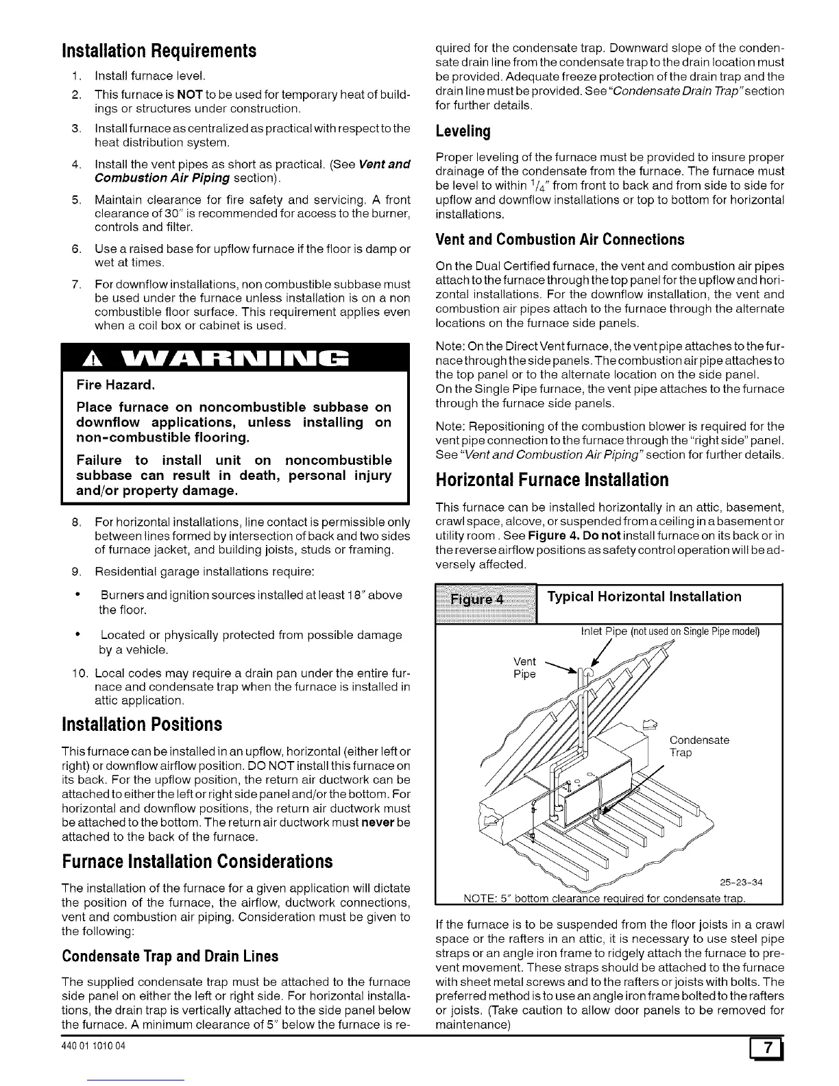
HorizontalFurnaceInstallation
This furnace can be installed horizontally in an attic, basement,
crawl space, alcove, or suspended from a ceiling in a basement or
utility room. See Figure 4. Do not install furnace on its back or in
the reverse airflow positions as safety control operation will be ad-
versely affected.
Typical Horizontal Installation
Inlet Pipe (notusedonSinglePipemodel)
Vent
Pipe
Condensate
Trap
25-23-34
NOTE: 5" bottom clearance required for condensate trap.
If the furnace is to be suspended from the floor joists in a crawl
space or the rafters in an attic, it is necessary to use steel pipe
straps or an angle iron frame to ridgely attach the furnace to pre-
vent movement. These straps should be attached to the furnace
with sheet metal screws and to the rafters or joists with bolts. The
preferred method isto use an angle iron frame bolted to the rafters
or joists. (Take caution to allow door panels to be removed for
maintenance)
 Loading...