6. Iforificeswerechanged,makesuretheyarecheckedfor
leakage.
6. Electrical Wiring
Electrical shock hazard.
Turn OFF electric power at fuse box or service
panel before making any electrical connections
and ensure a proper ground connection is made
before connecting line voltage.
Failure to do so can result in death, personal inju-
ry and/or property damage.
energized during continuous fan operation controlled by the elec-
tronic fan control.
Fan Control
The fan control is preset at the factory with a fixed blower ON
delay of 30 seconds in the heating mode. The blower OFF timing
is preset at 140 seconds. If desired, the fan OFF delay can be re-
set to obtain the longest delay times while still maintaining comfort
levels. See "Furnace Wiring Diagram".
PowerSupplyWiring
The furnace MUST be electrically wired and grounded in accor-
dance with local codes, or in the absence of local codes with the
latest edition of The National Electric Code, ANSI NFPA 70 and/or
The Canadian Electric Code CSA C22.1.
Field wiring connections must be made inside the furnace con-
nection box. A suitable strain relief should be used atthe point the
wires exit the furnace casing.
Copper conductors must be used. Line voltage wires should be
sized for the input amps stated on the rating plate. Furnace should
be connected to its own separate circuit.
Thermostat
Thermostat location has an important effect on the operation of
the unit. Follow instructions included with thermostat for correct
mounting and wiring.
Low voltage connections to furnace must be made on terminal
board to fan control.
Set thermostat heat anticipator in accordance with the Technical
Support Manual.
OptionalEquipment
All wiring from furnace to optional equipment MUST conform to
local codes or, in the absence of local codes with the latest edition
of The National Electric Code, ANSI NFPA 70 and/or The Cana-
dian Electric Code CSA C22.1. Install wiring in accordance with
manufacturer's instructions. The wiring MUST have a minimum
temperature rating of 105 ° C.
Humidifier/ElectronicAir Cleaner
The furnace is wired for humidifier and/or electronic air cleaner
connection.
CAUTION
Do NOT exceed 115V/0.8 amp. maximum current load
for both the EAC terminal and the HUM terminal
combined.
NOTE: The humidifier will be powered when the furnace is fired
and the circulating air blower comes on. The electronic air cleaner
will be powered anytime the air circulating blower is energized
during the heat mode. However, the electronic air cleaner is NOT
Fan Delay DIP Switch Settings
COOL ON DELAY: 6 SEC.
COOL OFF DELAY: 60 SEC.
HEAT ON DELAY: 30 SEC.
HEAT OFF DELAY
60SEC 100SEC 140SEC 180SEC
25-23-47
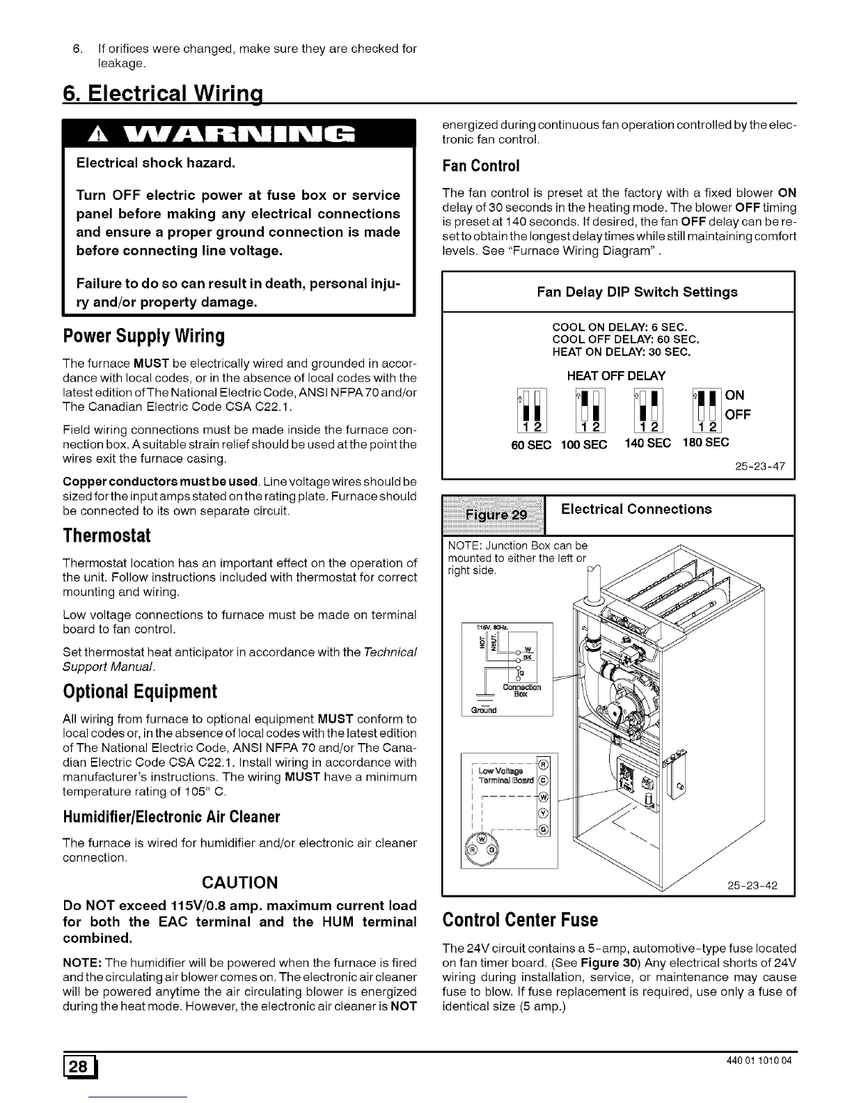
Electrical Connections
NOTE: Junction Box can be
mounted to either the left or
right side.
11_v. _0HL
Conn_ion
=
Q_nd
Control Center Fuse
25-23-42
The 24V circuit contains a 5-amp, automotive-type fuse located
on fan timer board. (See Figure 30) Any electrical shorts of 24V
wiring during installation, service, or maintenance may cause
fuse to blow. If fuse replacement is required, use only a fuse of
identical size (5 amp.)
[_ 440 01 101004
 Loading...