traponthefurnacemustbeprotectedfromfreezedamage.(See
Figure8troughFigure15)
1. Disconnectthe5/8"ODrubberhosefromtheventdrainfit-
tingthatislocateddownstreamofthecombustionblower.
Insertafunnelintothehoseandpourfour(4)ouncesof
sanitarytype(RV)antifreezeintothecondensatetrap.Re-
connectthe5/8"ODrubberhosetothestubonthevent
drainfitting.Securewiththehoseclamp.
2. Installation
2. Disconnect the 3/4" OD rubber hose from the condensate
trap. Insert a funnel into the hose and and pour four(4)
ounces of sanitary type (RV) antifreeze into the plastic
Transition box. Squeeze the hose together near the end
and quickly reconnect the 3/4" OD rubber hose to the stub
on the condensate trap. Secure with the hose clamp.
When you return home, your furnace will be ready to start, as it is
not necessary to drain the antifreeze from the furnace.
Poison carbon monoxide gas Hazard.
This furnace can NOT be common vented or
connected to any type B, BW or L vent or vent
connector, nor to any portion of a factory-built or
masonry chimney. If this furnace is replacing a
previously common-vented furnace, it may be
necessary to resize the existing vent and
chimney to prevent oversizing problems for the
other remaining appliance(s). See Venting and
Combustion Air Check in Gas Vent Installation
section. This furnace MUST be vented to the
outside.
Failure to properly vent this furnace or other
appliances can result in death, personal injury
and/or property damage.
LocationandClearances
Refer to Figure 1 or Figure 2 for typical installation and ba-
sic connecting parts required. Refer to Figure 4 for typical
horizontal direct vent installation and basic connecting
parts required. Supply and return air plenums and duct are
also required.
If furnace is a replacement, it is usually best to install the
furnace where the old one was. Choose the location or
evaluate the existing location based upon the minimum
clearance and furnace dimensions (Figure 3).
CAUTION
Special precautions MUST be made if installing
furnace in an area which may drop below freezing. This
can cause improper operation or damage to
equipment. If furnace environment has the potential of
freezing, the drain trap and drainline must be
protected. The use of electric heat tape or RV
antifreeze is recommended for these installations.
(See "Condensate Trap Freeze Protection Section")
Do NOT operate furnace in a corrosive atmosphere
containing chlorine, fluorine or any other damaging
chemicals. Refer to Combustion & Ventilation Air
section, Contaminated Combustion Air.
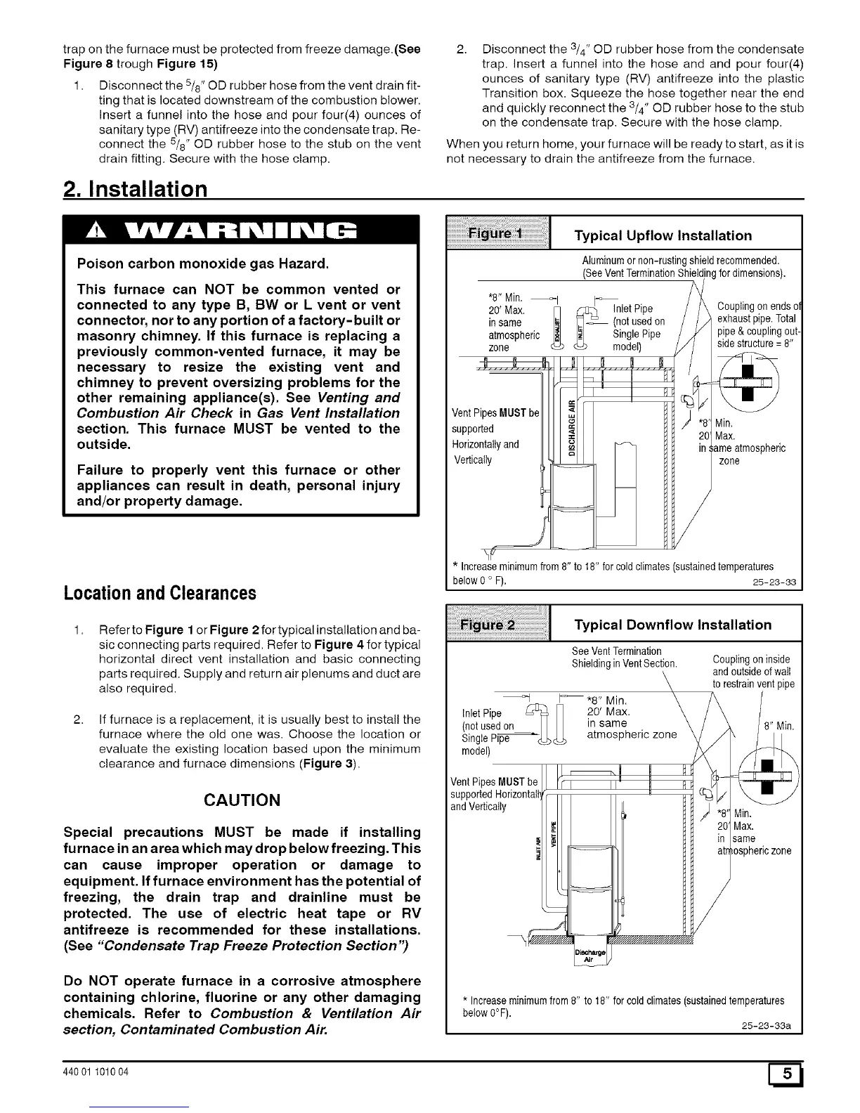
Typical Upflow Installation
AIuminumornon-rustingshietdrecommended.
(SeeVentTerminationShieldingfordimensions).
•8" Min. _ I_
20' Max. rq _ InletPipe Ooup%gonendsoi
in same <_ (_ _-_ (notusedon exhaustpipe.Total
atmospheric Single Pipe pipe& couplingout-
zone model) sidestructure= 8"
VentPipes MUSTbe
supported
Horizontallyand
Vertically
Min.
Max.
zone
* Increaseminimumfrom8" to 18" forcold climates (sustainedtemperatures
below0 o F). 25-23-33
Typical Downflow Installation
SeeVentTermination
ShieldinginVentSection.
I_ "8" Min.
Inlet Pipe _ _] 20' Max.
(notusedon_H in same
single pip-_(_ c_) atmospheric zone
model)
Vent PipesMUSTb
supportedHorizonta
and Vertically
\_ _ "////_/////////Y////_
Couplingoninside
and outsideofwait
torestrainventpipe
Min.
Max.
same
* Increaseminimumfrom8" to 18" for coldclimates(sustainedtemperatures
below0°F).
25-23-33a
440 01 101004
 Loading...