2. Gas input to burners MUST NOT exceed the rated input
shown on rating plate.
3. Do NOT allow minimum gas supply pressure to vary down-
ward. Doing so will decrease input to furnace. Refer to
Table 6 for normal gas supply and manifold pressures.
Gas
Type
Natural
LP
Gas Pressures Below 2000'
Supply Pressure
Recommended Max.
7" 14"
11" 14"
Important Note:
Manifold
Min. Pressure
4.5" 3.5"
11" 10"
With Propane gas, the rated input is obtained when
the BTU content is 2,500 BTU per cubic foot and
manifold pressure set at 10" W.C.
If Propane gas has a different BTU content, orifices
MUST be changed by licensed Propane installer.
Measured input can NOT exceed rated input.
Any major change in gas flow requires changing
burner orifice size.
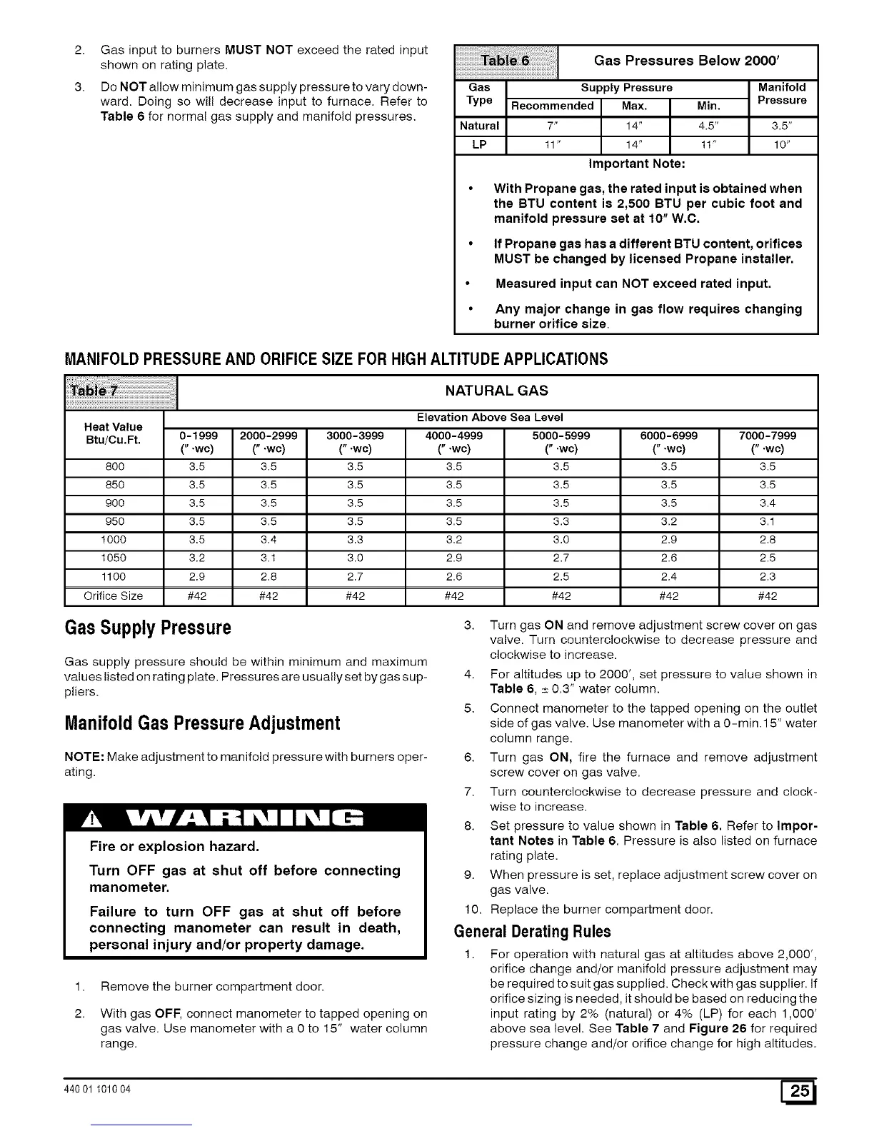
MANIFOLDPRESSURE AND ORIFICE SIZE FOR HIGH ALTITUDEAPPLICATIONS
..... i
i_Tai_!_i_!_i_!i_!ii!_iii!_i! NATURALGAS
Elevation Above Sea Level
Heat Value
Btu/Cu.Ft. 0-1999 2000-2999 3000-3999 4000-4999 5000-5999 6000-6999 7000-7999
(" .wc) (" .wc) (".wc) (".wc) (".wc) (".wc) (" .wc)
800 3.5 3.5 3.5 3.5 3.5 3.5 3.5
850 3.5 3.5 3.5 3.5 3.5 3.5 3.5
900 3.5 3.5 3.5 3.5 3.5 3.5 3.4
950 3.5 3.5 3.5 3.5 3.3 3.2 3.1
1000 3.5 3.4 3.3 3.2 3.0 2.9 2.8
1050 3.2 3.1 3.0 2.9 2.7 2.6 2.5
1100 2.9 2.8 2.7 2.6 2.5 2.4 2.3
Orifice Size #42 #42 #42 #42 #42 #42 #42
GasSupply Pressure
Gas supply pressure should be within minimum and maximum
values listed on rating plate. Pressures are usually set by gas sup-
pliers.
ManifoldGas PressureAdjustment
NOTE: Make adjustment to manifold pressure with burners oper-
ating.
Fire or explosion hazard.
Turn OFF gas at shut off before connecting
manometer.
Failure to turn OFF gas at shut off before
connecting manometer can result in death,
personal injury and/or property damage.
1.
2.
Remove the burner compartment door.
With gas OFF, connect manometer to tapped opening on
gas valve. Use manometer with a 0 to 15" water column
range.
3. Turn gas ON and remove adjustment screw cover on gas
valve. Turn counterclockwise to decrease pressure and
clockwise to increase.
4. For altitudes up to 2000', set pressure to value shown in
Table 6, ± 0.3" water column.
5. Connect manometer to the tapped opening on the outlet
side of gas valve. Use manometer with a 0-rain.15" water
column range.
6. Turn gas ON, fire the furnace and remove adjustment
screw cover on gas valve.
7. Turn counterclockwise to decrease pressure and clock-
wise to increase.
8. Set pressure to value shown in Table 6. Refer to Impor-
tant Note8 in Table 6. Pressure is also listed on furnace
rating plate.
9. When pressure is set, replace adjustment screw cover on
gas valve.
10. Replace the burner compartment door.
General DeraUngRules
1. For operation with natural gas at altitudes above 2,000',
orifice change and/or manifold pressure adjustment may
be required to suit gas supplied. Check with gas supplier. If
orifice sizing is needed, it should be based on reducing the
input rating by 2% (natural) or 4% (LP) for each 1,000'
above sea level. See Table 7 and Figure 26 for required
pressure change and/or orifice change for high altitudes.
44001 101004 [_
 Loading...