Example
Natural Gas No.of Seconds | TimePer Cubic BTUPer
BTUContent Per Hour t Footin Seconds Hour1,000 3,600 48 75,000
1,000 x 3,600 + 48 = 75,000 BTUH
3. Time how many seconds it takes the smallest dial on the
gas meter to make one complete revolution. Refer to Ex-
ample.
4. Relight all appliances and ensure all pilots are operating.
NOTE: If meter uses a 2 cubic foot dial, divide results (seconds)
by two.
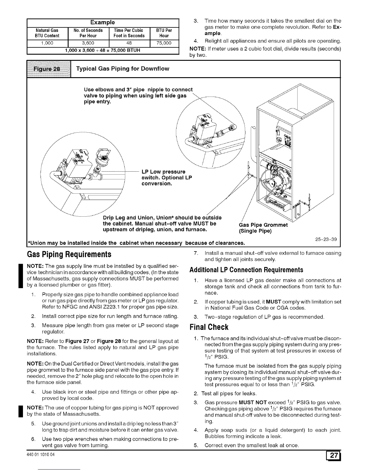
Typical Gas Piping for Downflow
Use elbows and 3" pipe nipple to connect
valve to piping when using left side gas
pipe entry.
LP Low pressure
switch. Optional LP
conversion.
Drip Leg and Union, Union* should be outside
the cabinet. Manual shut-off valve MUST be
upstream of dripleg, union, and furnace.
Gas Pipe Grommet
(Single Pipe)
*Union may be installed inside the cabinet when necessary because of clearances.
Gas Piping Requirements
NOTE: The gas supply line must be installed by a qualified ser-
vice technician in accordance with all building codes, (In the state
of Massachusetts, gas supply connections MUST be performed 1.
by a licensed plumber or gas fitter).
1. Properly size gas pipe to handle combined appliance load
or run gas pipe directly from gas meter or LP gas regulator. 2.
Refer to NFGC and ANSI Z223.1 for proper gas pipe size.
2. Install correct pipe size for run length and furnace rating.
3. Measure pipe length from gas meter or LP second stage
regulator.
NOTE: Refer to Figure 27 or Figure 28 for the general layout at
the furnace. The rules listed apply to natural and LP gas pipe
installations.
NOTE: On the Dual Certified or Direct Vent models, install the gas
pipe grommet to the furnace side panel with the gas pipe entry. If
needed, remove the 2" hole plug and relocate to the open hole in
the furnace side panel.
4. Use black iron or steel pipe and fittings or other pipe ap-
proved by local code.
I OTE: The use of copper tubing for gas piping is NOT approved
by the state of Massachusetts.
5. Use ground joint unions and install a drip leg no less than 3"
long to trap dirt and moisture before it can enter gas valve. 4.
6. Use two pipe wrenches when making connections to pre-
vent gas valve from turning. 5.
440 01 101004
25-23-39
7. Install a manual shut-off valve external to furnace casing
and tighten all joints securely.
Additional LP Connection Requirements
Have a licensed LP gas dealer make all connections at
storage tank and check all connections from tank to fur-
nace.
If copper tubing is used, it MUST comply with limitation set
in National Fuel Gas Code or CGA codes.
3. Two-stage regulation of LP gas is recommended.
FinalCheck
1. The furnace and its individual shut-off valve must be discon-
nected from the gas supply piping system during any pres-
sure testing of that system at test pressures in excess of
1/2" PSlG.
The furnace must be isolated from the gas supply piping
system by closing its individual manual shut-off valve dur-
ing any pressure testing of the gas supply piping system at
test pressures equal to or less than 1/2" PSlG.
2. Test all pipes for leaks.
3. Gas pressure MUST NOT exceed t/2" PSIG to gas valve,
Checking gas piping above t/2" PSIG requires the furnace
and manual shut-off valve to be disconnected during test-
ing.
Apply soap suds (or a liquid detergent) to each joint,
Bubbles forming indicate a leak.
Correct even the smallest leak at once.
 Loading...