Horizontal Left Installations (Single Pipe & Direct Vent NgMP1 & NgMP2 Models)
Plastic
Caps
Pressure Switch,
Blower Rubber
Plug
Transition
Grommet
Pressure Switch
Transition
Pressure Switch,
Supply
Air
?_> Inlet
/
Combustion
Air Pipe,
NgMP2 ONLY
Vent Fitting
& Clamps
Pressure Switch
Hose, Blower
Combustion Blower
5/8" Hose &
Clamps
Return
Air
Combustion Blower
(Rotate 180 ° for Right Side)
3/4" Hose
& Clamps
Condensate
Trap & Gasket
Caps
dwg 25-23-58
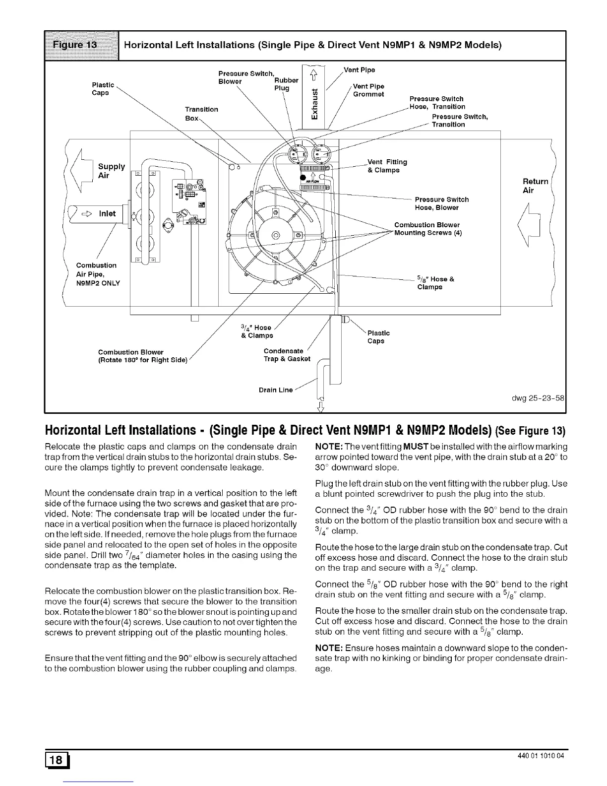
HorizontalLeft Installations- (SinglePipe& DirectVentN9MP1& N9MP2Models)(See Figure 13)
Relocate the plastic caps and clamps on the condensate drain
trap from the vertical drain stubs to the horizontal drain stubs. Se-
cure the clamps tightly to prevent condensate leakage.
Mount the condensate drain trap in a vertical position to the left
side of the furnace using the two screws and gasket that are pro-
vided. Note: The condensate trap will be located under the fur-
nace in a vertical position when the furnace is placed horizontally
on the left side. If needed, remove the hole plugs from the furnace
side panel and relocated to the open set of holes in the opposite
side panel. Drill two 7/64" diameter holes in the casing using the
condensate trap as the template.
Relocate the combustion blower on the plastic transition box. Re-
move the four(4) screws that secure the blower to the transition
box. Rotate the blower 180 ° so the blower snout is pointing up and
secure with the four(4) screws. Use caution to not over tighten the
screws to prevent stripping out of the plastic mounting holes.
Ensure that the vent fitting and the 90 ° elbow is securely attached
to the combustion blower using the rubber coupling and clamps.
NOTE: The vent fitting MUST be installed with the airflow marking
arrow pointed toward the vent pipe, with the drain stub at a 20° to
30 ° downward slope.
Plug the left drain stub on the vent fitting with the rubber plug. Use
a blunt pointed screwdriver to push the plug into the stub.
Connect the 3/4" OD rubber hose with the 90° bend to the drain
stub on the bottom of the plastic transition box and secure with a
3/4" clamp.
Route the hose to the large drain stub on the condensate trap. Cut
off excess hose and discard. Connect the hose to the drain stub
on the trap and secure with a 3/4" clamp.
Connect the 5/8" OD rubber hose with the 90° bend to the right
drain stub on the vent fitting and secure with a 5/8" clamp.
Route the hose to the smaller drain stub on the condensate trap.
Cut off excess hose and discard. Connect the hose to the drain
stub on the vent fitting and secure with a 5/8" clamp.
NOTE: Ensure hoses maintain a downward slope to the conden-
sate trap with no kinking or binding for proper condensate drain-
age.
[_1 440 01 101004
 Loading...