2. SAFE INSTALLATION REQUIREMENTS
FIRE AND ELECTRICAL SHOCK HAZARD
Failure to carefully read and follow all instructions in this
manual could result in furnace malfunction, personal
injury, death and/or property damage.
Installation or repairs made by unqualified persons can
result in hazards to you and others. Installation MUST
conform with local building codes or, in the absence of
local codes, with the National Electrical Code
NFPA70-2005 or in Canada and CSA C.22.1 - Canadian
Electrical Code Part 1.
The information contained in this manual is intended for
use by a qualified service technician familiar with safety
procedures and equipped with the proper tools and test
instruments.
• Seal supply and return air ducts.
• Check to see that filters are installed correctly and are
the proper type an size.
NOTE: It is the personal responsibility and obligation of the
customer to contact a qualified installer to ensure that the
installation is adequate and conforms to governing codes
and ordinances.
3. LOCATING THE UNIT
ACCESS PANELS
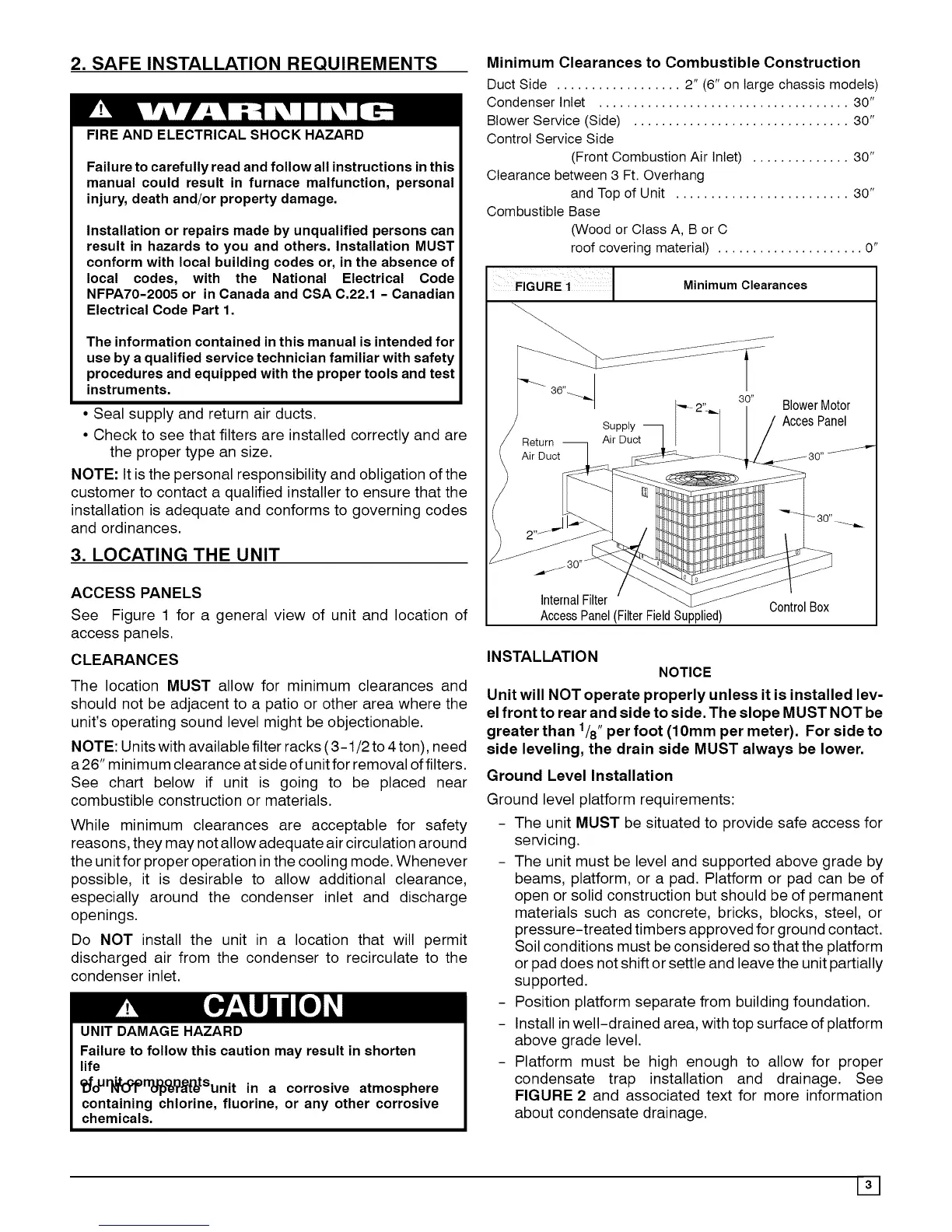
See Figure 1 for a general view of unit and location of
access panels.
CLEARANCES
The location MUST allow for minimum clearances and
should not be adjacent to a patio or other area where the
unit's operating sound level might be objectionable.
NOTE: Units with available filter racks (3-1/2 to 4 ton), need
a26" minimum clearance at side of unit for removal of filters.
See chart below if unit is going to be placed near
combustible construction or materials.
While minimum clearances are acceptable for safety
reasons, they may not allow adequate air circulation around
the unit for proper operation inthe cooling mode. Whenever
possible, it is desirable to allow additional clearance,
especially around the condenser inlet and discharge
openings.
Do NOT install the unit in a location that will permit
discharged air from the condenser to recirculate to the
condenser inlet.
UNIT DAMAGE HAZARD
Failure to follow this caution may result in shorten
life
Ci_oU_ltooprr_°e_r_Sunit in a corrosive atmosphere
containing chlorine, fluorine, or any other corrosive
chemicals.
Minimum Clearances to Combustible Construction
Duct Side .................. 2" (6" on large chassis models)
Condenser Inlet .................................... 30"
Blower Service (Side) ............................... 30"
Control Service Side
(Front Combustion Air Inlet) .............. 30"
Clearance between 3 Ft. Overhang
and Top of Unit ......................... 30"
Combustible Base
(Wood or Class A, B or C
roof covering material) ..................... 0"
FIGURE 1J Minimum Clearances
_..
Return _ ASuPDPluYc!j_ AccesPanel
-1_ _i_tDr_t___ _ t _.... "_ 2"_ Blower Motor
Air Duct [_:_ _ .... _ .J/30 ....
' __'_:_:_ 30
)
nerna I er
AccessPanel(FilterFieldSupplied)
INSTALLATION
NOTICE
Unit will NOT operate properly unless it is installed lev-
el front to rear and side to side. The slope MUST NOT be
greater than 1/8" per foot (10mm per meter). For side to
side leveling, the drain side MUST always be lower.
Ground Level Installation
Ground level platform requirements:
- The unit MUST be situated to provide safe access for
servicing.
- The unit must be level and supported above grade by
beams, platform, or a pad. Platform or pad can be of
open or solid construction but should be of permanent
materials such as concrete, bricks, blocks, steel, or
pressure-treated timbers approved for ground contact.
Soil conditions must be considered so that the platform
or pad does not shift or settle and leave the unit partially
supported.
- Position platform separate from building foundation.
- Install inwell-drained area, with top surface of platform
above grade level.
- Platform must be high enough to allow for proper
condensate trap installation and drainage. See
FIGURE 2 and associated text for more information
about condensate drainage.