6. AIRFLOW ADJUSTMENT
CIRCULATING AIR BLOWER SPEEDS
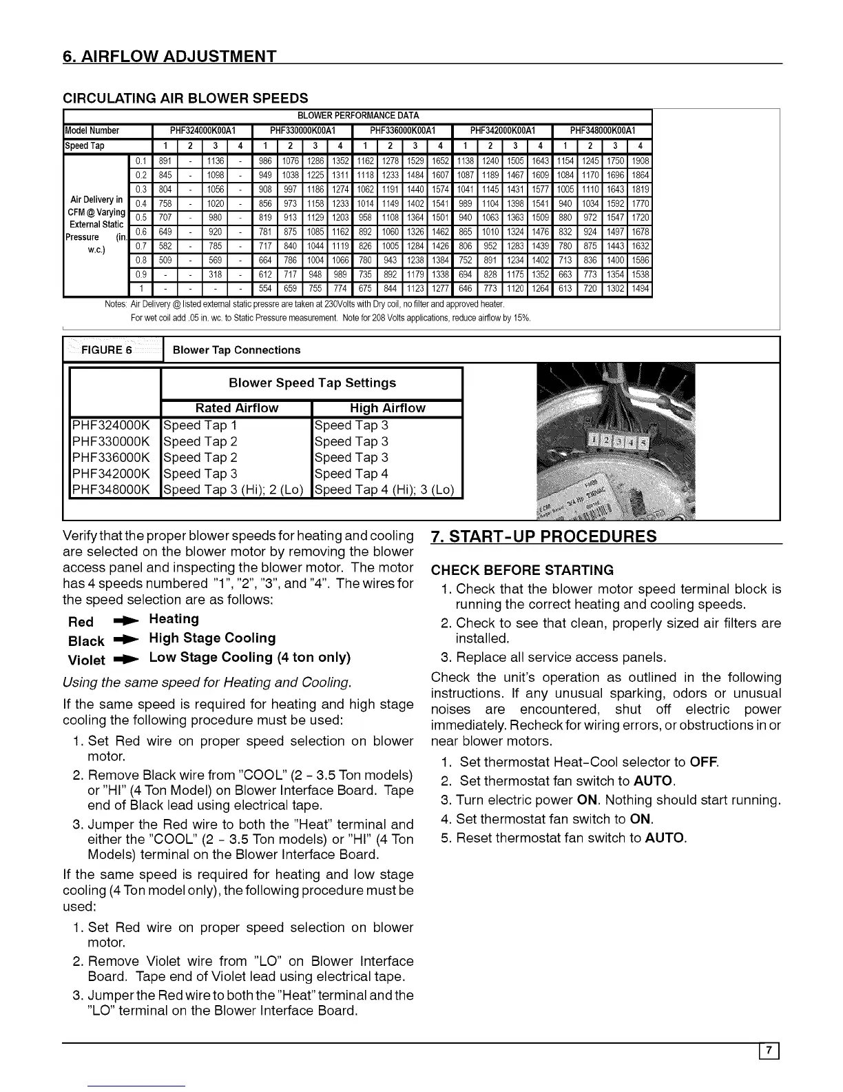
BLOWERPERFORMANCEDATA
AirDeliveryin
CFM@ Varying
ExternalStatic
Pressure (in,
W.C.)
_odel Number PHF324000K00AI PHF330000K00AI
3peedTap 1 2 3 4 1 2 3 4
0.1 891 1136 986 1076 1286 1352
0.2 845 1098 949 1038 1225 1311
0.3 804 1056 908 997 1186 1274
0.4 758 1020 856 973 1158 1233
0.5 707 980 819 913 1129 1203
0.6 649 920 781 875 1085 1162
0.7 582 785 717 840 1044 1119
0.8 509 569 664 786 1004 1066
0.9 318 612 717 948 989
1 554 659 755 774
PHF336000K00A1
1 2 3 4
1162 1278 1529 1652
1118 1233 1484 1607
1062 1191 1440 1574
1014 1149 1402 1541
958 1108 1364 1501
892 1060 1326 1462
826 1005 1284 1426
780 943 1238 1384
735 892 1179 1338
675 844 1123 1277
PHF342000K00A1 PHF348000K00A1
1 2 3 4 1 2 3 4
1138 1240 1505 1643 1154 1245 1750 1908
1087 1189 1467 1609 1084 1170 1696 1864
1041 1145 1431 1577 1005 1110 1643 1819
989 1104 1398 1541 940 1034 1592 1770
940 1063 1363 1509 880 972 1547 1720
865 1010 1324 1476 832 924 1497 1678
806 952 1283 1439 780 875 1443 1632
752 891 1234 1402 713 836 1400 1586
694 828 1175 1352 663 773 1354 1538
646 773 1120 1264 613 720 1302 1494
Notes:Air Delivery@listed externalstatic pressrearetaken at230Voltswith Drycoil, no filterand approvedheater.
Forwet coiladd .05in. wc. to Static Pressuremeasurement.Notefor 208Volts applications,reduceairflowby15%.
FIGURE 6
PHF324000K
PHF330000K
PHF336000K
PHF342000K
PHF348000K
Blower Tap Connections
Blower Speed Tap Settings
Rated Airflow
Speed Tap 1
Speed Tap 2
Speed Tap 2
Speed Tap 3
Speed Tap 3(Hi);2(Lo)
High Airflow
Speed Tap 3
Speed Tap 3
Speed Tap 3
Speed Tap 4
Speed Tap 4 (Hi);3(Lo)
I
Verify that the proper blower speeds for heating and cooling
are selected on the blower motor by removing the blower
access panel and inspecting the blower motor. The motor
has 4 speeds numbered "1", "2", "3", and "4". The wires for
the speed selection are as follows:
Red _ Heating
Black _ High Stage Cooling
Violet _ Low Stage Cooling (4 ton only)
Using the same speed for Heating and Cooling.
If the same speed is required for heating and high stage
cooling the following procedure must be used:
1. Set Red wire on proper speed selection on blower
motor.
2. Remove Black wire from "COOL" (2 - 3.5 Ton models)
or "HI" (4 Ton Model) on Blower Interface Board. Tape
end of Black lead using electrical tape.
3. Jumper the Red wire to both the "Heat" terminal and
either the "COOL" (2 - 3.5 Ton models) or "HI" (4 Ton
Models) terminal on the Blower Interface Board.
If the same speed is required for heating and low stage
cooling (4 Ton model only), the following procedure must be
used:
1. Set Red wire on proper speed selection on blower
motor.
2. Remove Violet wire from "LO" on Blower Interface
Board. Tape end of Violet lead using electrical tape.
3. Jumper the Red wire to both the "Heat" terminal and the
"LO" terminal on the Blower Interface Board.
7. START-UP PROCEDURES
CHECK BEFORE STARTING
1. Check that the blower motor speed terminal block is
running the correct heating and cooling speeds.
2. Check to see that clean, properly sized air filters are
installed.
3. Replace all service access panels.
Check the unit's operation as outlined in the following
instructions. If any unusual sparking, odors or unusual
noises are encountered, shut off electric power
immediately. Recheck for wiring errors, or obstructions in or
near blower motors.
1. Set thermostat Heat-Cool selector to OFE
2. Set thermostat fan switch to AUTO.
3. Turn electric power ON. Nothing should start running.
4. Set thermostat fan switch to ON.
5. Reset thermostat fan switch to AUTO.