REDUCED EQUIPMENT LIFE HAZARD
Failure to follow these precautions could result in
damage to the unit being installed.
1) Make all electrical connections in accordance with
National Electric code (NEC) NFPa 70 and local electrical
codes governing such wiring. In Canada, all electrical
connections must be in accordance with CSA standard
C22.1, Canadian Electrical Code Part 1, and applicable
local codes. Refer to unit wiring diagram.
2) Use only copper conductor for connections
between field-supplied electrical disconnect switch and
unit. DO NOT USE ALUMINUM WIRE.
3) Be sure that high-voltage power to unit is within
operating voltage range indicated on unit rating plate.
4) Do not damage internal components when drilling
through any panel to mount electrical hardware,
conduit, etc. Consult local power company for
correction of improper voltage and/or phase imbalance.
Disconnect Switch
The unit must have separate electrical service with a
field-supplied, waterproof, disconnect switch mounted at,
or within sight from, the unit. Refer tothe unit rating plate for
maximum fuse/circuit breaker size and minimum circuit
amps (ampacity) for wire sizing.
Ground Connections
Do NOT complete line voltage connections until unit is
permanently grounded. All line voltage connections and the
ground connection MUST be made with copper wire.
A ground lug is installed in the control box area for the
ground connection. Use a copper conductor of the
appropriate size from the unit to a grounded connection in
the electrical service panel or a properly driven and
electrically grounded ground rod. See warning above.
Line Voltage Wiring - (Wiring Diagrams page 12 & 13)
Connections for line voltage are made in the unit control box
area. Refer to wiring diagram located on the Access panel.
For access, remove the burner access panel.
1. Run the high voltage (L1, L2) and ground leads into the
control box.
2. Connect ground lead to chassis ground connection.
3. Connect L1 to pressure lug connection 11 of the
compressor contactor.
4. Connect L2 to pressure lug connection 23 of the
compressor contactor.
Thermostat / Low Voltage Wiring
Location of the thermostat has an important effect on home
comfort. FOLLOW THE THERMOSTAT INSTRUCTION
MANUAL FOR CORRECT LOCATION, MOUNTING, AND
WIRING.
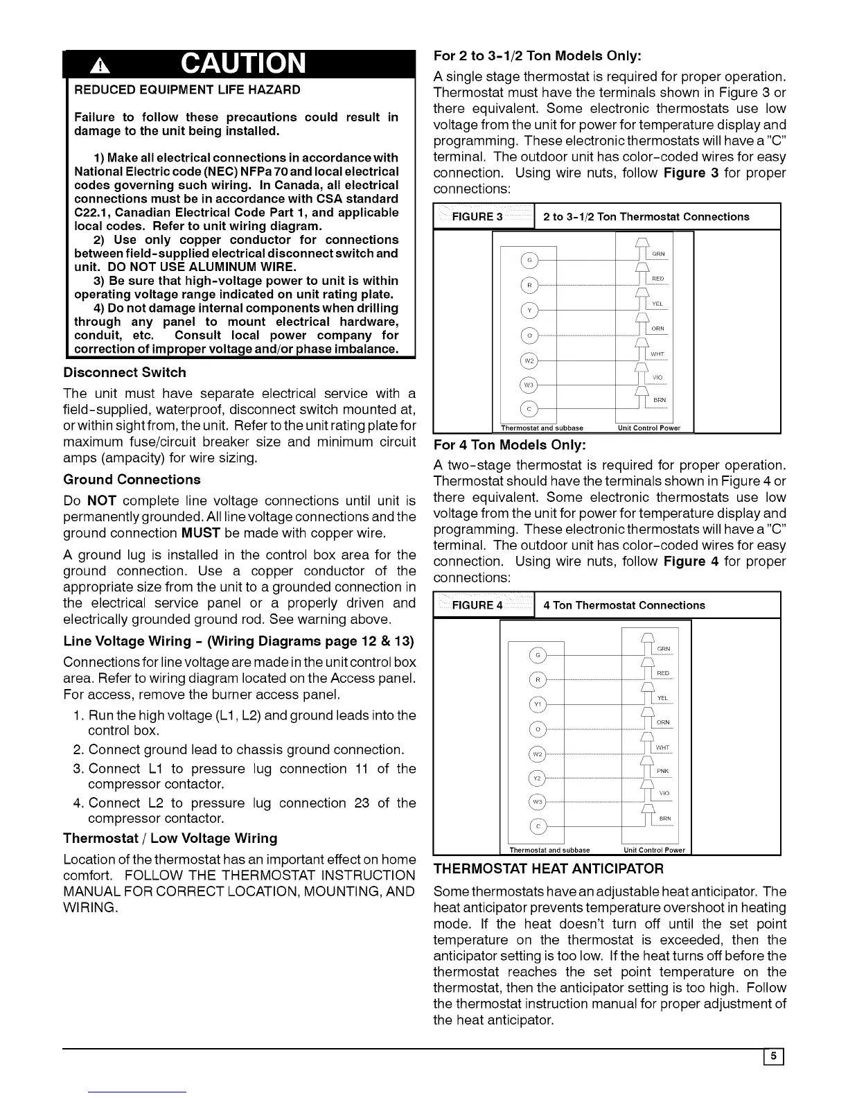
For 2 to 3-1/2 Ton Models Only:
A single stage thermostat is required for proper operation.
Thermostat must have the terminals shown in Figure 3 or
there equivalent. Some electronic thermostats use low
voltage from the unit for power for temperature display and
programming. These electronic thermostats will have a "C"
terminal. The outdoor unit has color-coded wires for easy
connection. Using wire nuts, follow Figure 3 for proper
connections:
FIGURE 3 2 to 3-1/2 Ton Thermostat Connections
Thermostat and subbase Unit Control Power
For 4 Ton Models Only:
A two-stage thermostat is required for proper operation.
Thermostat should have the terminals shown in Figure 4 or
there equivalent. Some electronic thermostats use low
voltage from the unit for power for temperature display and
programming. These electronic thermostats will have a "C"
terminal. The outdoor unit has color-coded wires for easy
connection. Using wire nuts, follow Figure 4 for proper
connections:
FIGURE 4 4 Ton Thermostat Connections
Thermostat and subbase Unit Control Power
THERMOSTAT HEAT ANTICIPATOR
Some thermostats have an adjustable heat anticipator. The
heat anticipator prevents temperature overshoot in heating
mode. If the heat doesn't turn off until the set point
temperature on the thermostat is exceeded, then the
anticipator setting istoo low. If the heat turns off before the
thermostat reaches the set point temperature on the
thermostat, then the anticipator setting is too high. Follow
the thermostat instruction manual for proper adjustment of
the heat anticipator.