RS-485 Reader Locations
As two RS-485 readers can be connected to the same RS-485 reader port, configuration of the green and
orange wires uniquely identifies the reader, and determines which is the entry reader and which is the exit
reader.
Location Configuration
Entry Green and orange wires not connected.
Exit Green and orange wires connected together.
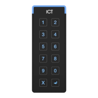
RS-485 Reader Connection
The connection of a single RS-485 reader to a reader expander in entry only mode.
Shield is frame
grounded at
one point
Shielded Cable
RED
BLACK
GREEN
WHITE
ORANGE
BROWN
BLUE
YELLOW
VIOLET
Shield not
connected
SHIELD
1 2
3 4
5 6
7 8
9 0
X
V+
V-C BZ L2 L1
D1/ D0/
NB
NA
When the green and orange wires are not connected together, the reader defaults to an entry reader.
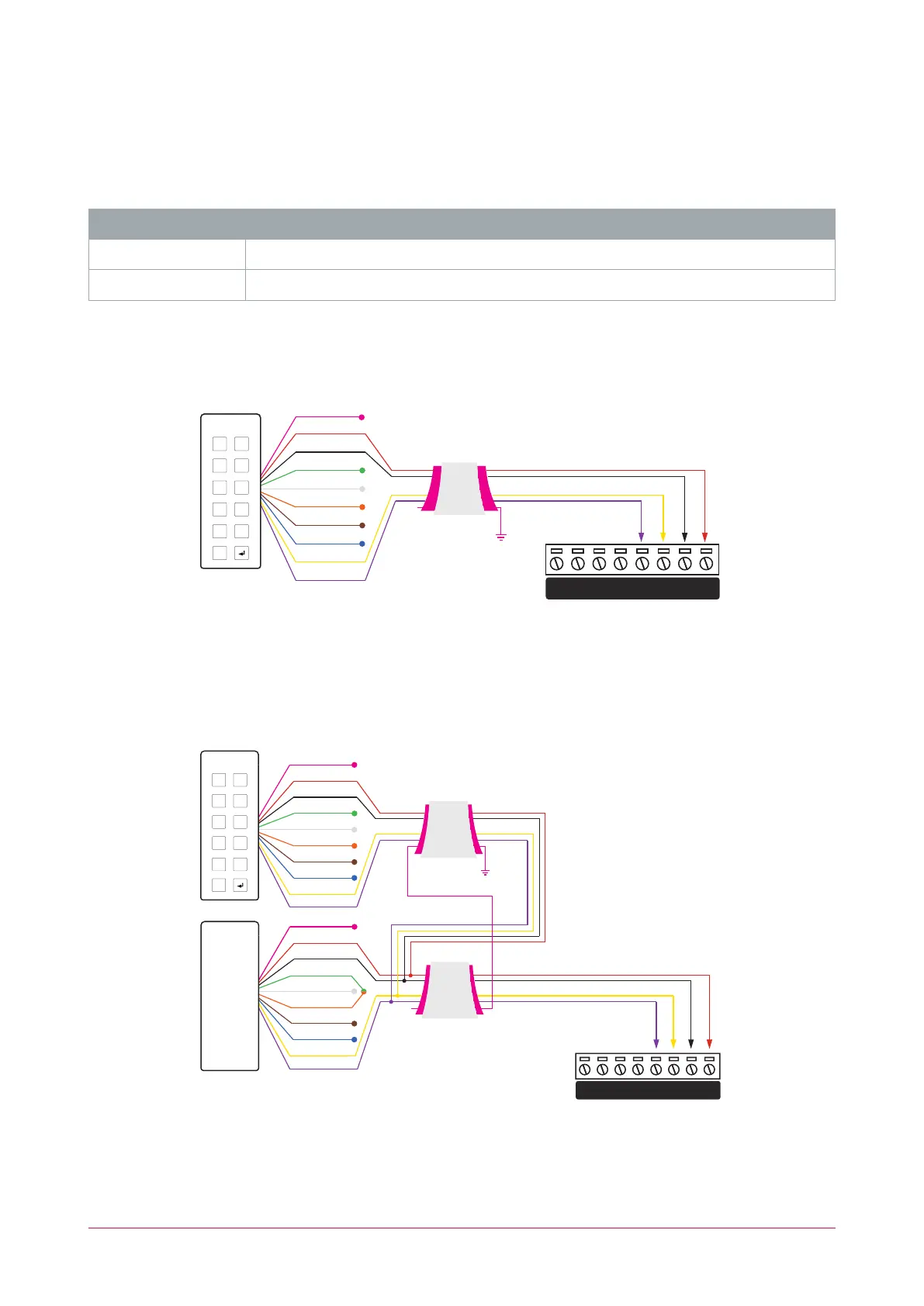
RS-485 Reader Connection (Entry/Exit)
The connection of two RS-485 readers to a reader expander providing an entry/exit configuration.
Shield is frame
grounded at
one point
Shielded Cable
Shielded Cable
RED
BLACK
GREEN
WHITE
ORANGE
BROWN
BLUE
YELLOW
SHIELD
RED
BLACK
GREEN
SHIELD
WHITE
ORANGE
BROWN
BLUE
YELLOW
Shield not
connected
VIOLET
VIOLET
ENTRY
EXIT
V+
V-C BZ L2 L1
D1/ D0/
NB
NA
1 2
3 4
5 6
7 8
9 0
X
The exit reader has the green and orange wires connected together.
PRX-TSEC Range | tSec Multi-Technology Card Reader with Bluetooth® Technology | Installation Manual 16