13
Installation and Servicing
SECTION 1 - GENERAL
Model 18 30
Max CH Output kW 18 30.3
Water ow rate l/min 13 21.5
(gal/min) (2.8) (4.7)
Temp differential
o
C 20 20
Head available kPa 44.12 18.63
for system (ft.w.g.) (14.7) (6.2)
General
1. The installation must comply with all relevant national and local
regulations.
2. The installation should be designed to work with flow
temperatures of up to 86
o
C.
3.
All components of the system must be suitable for a working
pressure of 300kPa and a maximum design temperature of 110
o
C.
Extra care should be taken in making all connections so that
the risk of leakage is minimised.
The following components are incorporated within the appliance:
a. Circulating pump.
b. Safety valve, with a non-adjustable preset lift pressure of
300kPa.
c. Pressure gauge, covering a range of 0 to 400kPa.
d. An 8-litre expansion vessel, with an initial charge pressure
of 75kPa.
4. Filling Water Connection. Mains water ll lines must be
installed with an Automatic Filling Valve - Available from
Hunt Heating. After following the below lling instructions the
Automatic Filling Valve MUST be turned off.
The maximum cold water capacity of the system should not
exceed 143 litres. This is the maximum system volume for
the boiler expansion vessel. If the capacity of the vessel is
not considered sufcient for this, or for any other reason, an
additional vessel MUST be installed on the return to the boiler.
Guidance on vessel sizing is given in table opposite.
5. Filling
After installation of an Autoll valve and required backow
prevention, the system may be lled by the following method:
i. Thoroughly ush out the whole system with cold water.
ii. Fill and vent the system until the pressure gauge registers
150kPa, and examine for leaks.
iii. Check the operation of the safety valve by raising the water
pressure until the valve lifts. This should occur within 30kPa of
the preset lift pressure.
iv. Release water from the system until it reaches 100kPa.
Isolate main water supply by turning off autoll valve.
Notes
a. The method of lling, relling, topping up or ushing sealed circuits
from the mains supply must be done in accordance with national and
local regulations ie: proper backow prevention must be in place.
b. Antifreeze uid, corrosion and scale inhibitor uids suitable for use
with boilers having aluminium heat exchangers may be used in the
central heating system.
c. The use of suitable inhibitor fluids is mandatory. For boiler
changeovers on existing systems all existing system components
must be thoroughly ushed with appropriate chemicals/power ush
pumps prior to installing the new boiler. Failure to adhere to either
of the above will void boiler warranty as per T&C’s.
d. The use of the correct gas isolation valve is mandatory.
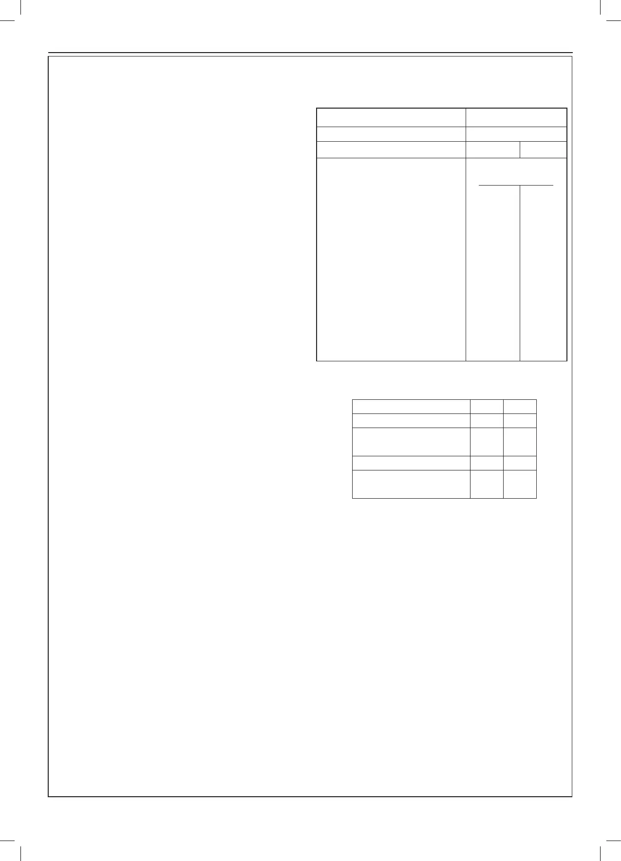
1.18 SYSTEM REQUIREMENTS - CENTRAL HEATING
Safety valve setting kPa 300
Vessel charge pressure kPa 50 to 75
System pre-charge pressure kPa None 100
System volume Expansion vessel
(litres) volume (litres)
25 1.6 1.8
50 3.1 3.7
75 4.7 5.5
100 6.3 7.4
125 7.8 9.2
150 9.4 11.0
175 10.9 12.9
190 11.9 14.0
200 12.5 14.7
250 15.6 18.4
300 18.8 22.1
For other system volumes
multiply by the factor across 0.063 0.074