19
Installation and Servicing
SECTION 2 - INSTALLATION
3G9495
X
Section
through wall
Note. Check all of the hole
positions before drilling.
Side flue only
5" diameter hole
Rear flue only
5" diameter hole
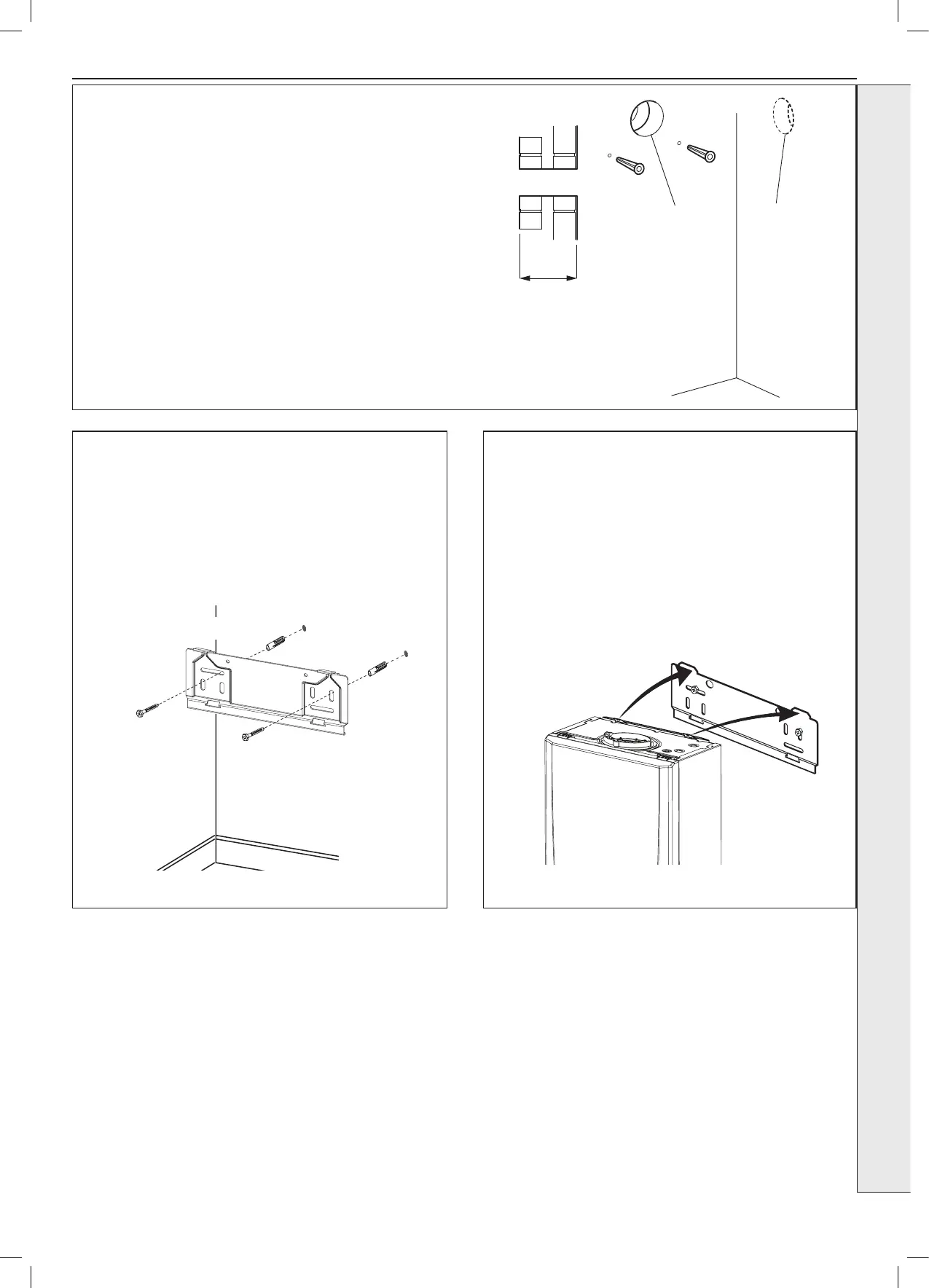
2.7 PREPARING THE WALL
IMPORTANT.
Ensure that, during the cutting operation, masonry falling
outside of the building does not cause damage or personal
injury.
1. Cut the ue hole (preferably with a 5” core boring tool),
ensuring that the hole is square to the wall.
Both wall faces immediately around the cut hole should be
at.
2. Drill 2 mounting holes (marked from template) with a 7.5mm
/ 8mm masonry drill and insert the plastic plugs, provided,
for the wall mounting plate.
3. Locate 2 No.14 x 50mm screws in the wall mounting plate
(one at each side, in any of the 3 holes provided at each
side) and screw home. Ensure mounting bracket is level.
2.8 FITTING THE WALL MOUNTING
BRACKET - INTERNAL BOILER
2.9 MOUNTING THE BOILER - INTERNAL
1. Ensure the plastic plug is removed from the CH
connections before mounting the boiler.
Caution: Water may discharge from open pipes.
2. Lift the boiler onto the wall mounting plate (refer to the
Introduction Section for safe handling advice), locating it
over the two tabs.
Screw the wall mounting plate to the wall using 2 wall
plugs (previously tted) with the 2 screws provided.
Choose one of the 2 sets of slots in left and right bank.
Ensuring that at least one of the screws is tted into a top
slot.