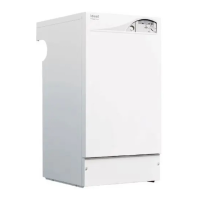
IMPORTANT. The boiler MUST be installed in a vertical position
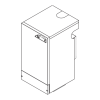
Dimension X - Wall thickness.
Dimension L - Wall thickness plus boiler spacing.
19
DETERMINING THE FLUE LENGTH AND FLUE PACKS REQUIRED
FLUE KITS
Pack B - supplied as standard.
Finishing Kit - supplied as an optional extra.
Screw Kit -
Pack D
Refer to ‘Flue Extension Ducts’.
Note. The ue duct MUST be inclined at 1.5 degrees
to the horizontal to allow condensate to drain back into
the boiler and out through the condensate drain. (Only
necessary if using one or more ‘D’ extension duct packs)
Notes.
1. It is recommended that a
support bracket is tted for
every 1 metre of extension
pipe used and a bracket
should be used at every joint,
to ensure pipes are held at
the correct angle.
If a slip joint coupling is to be
used then a bracket should
be used to secure the collar.
2. Only use water as lubricant
during assembly.
Note. MAXIMUM FLUE LENGTHS:
HE15, 18 AND 24 - 6M (HORIZONTAL FLUE)
HE30 AND 36 - 3M (HORIZONTAL FLUE)
HE15, 18 AND 24 - 8M (VERTICAL FLUE)
HE 30 AND 36 - 5M (VERTICAL FLUE)
90
O
ELBOW KIT (EQUIVALENT FLUE LENGTH RESISTANCE = 1.5M)
45
O
ELBOW KIT (EQUIVALENT FLUE LENGTH RESISTANCE = 1.0M)
20
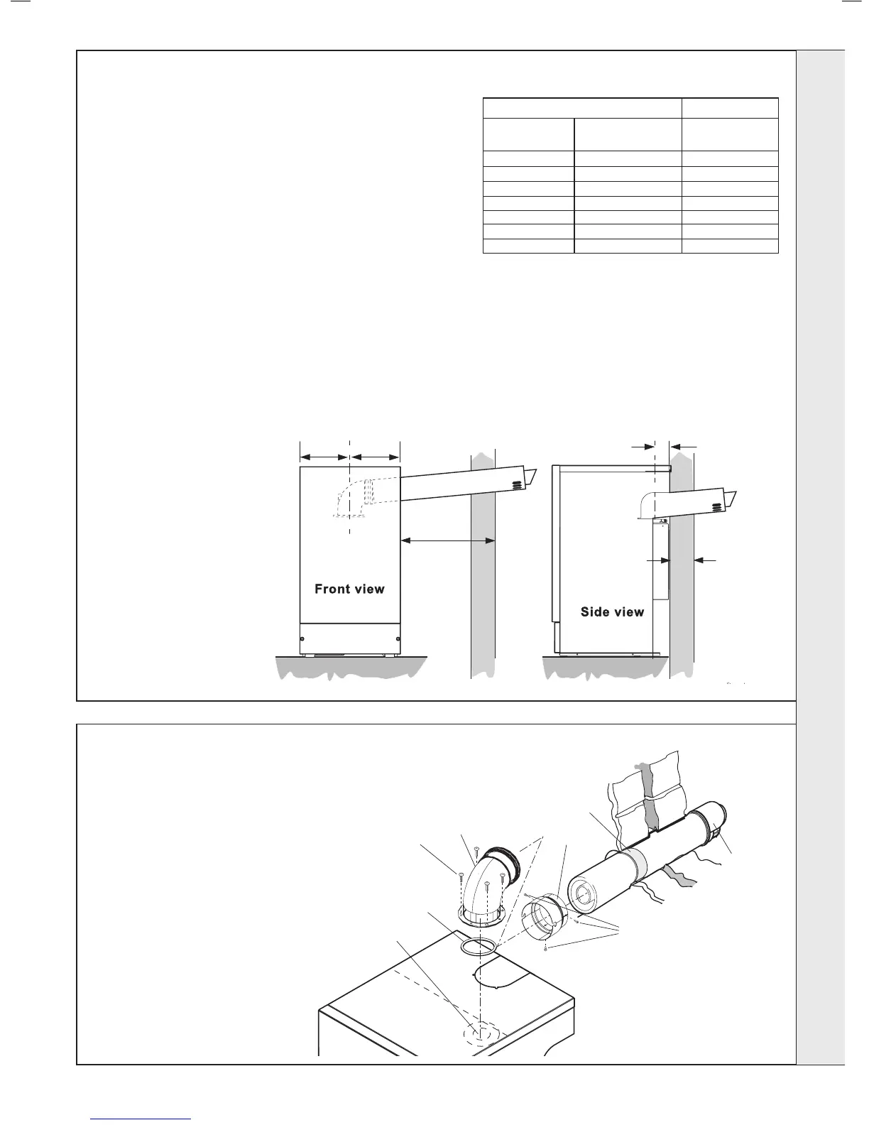
FLUE ASSEMBLY - Exploded View
LEGEND
1.
2. Flue turret
3.
4. Flue connector
5. Flue connector screws
6. Turret gasket
7. Foam sealing tape
Side 545mm (21
1
/
2
”)
Rear 705mm (27
3
/
4
”)
Rear ue arrangement shown
Total Flue length dimension Flue
Rear ue Side ue Extra packs
dim. X+75 dim. L+225 required
Up to 775 mm Up to 775 mm none
INSTALLATION
 Loading...