21
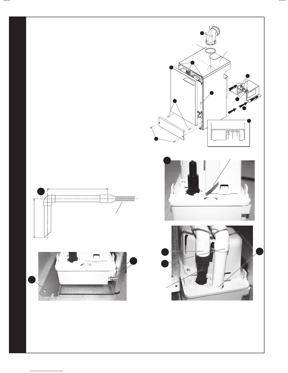
MOUNTING THE BOILER ONTO THE PRE-PIPING FRAME
NOTE. USE THE BOILER PACKAGING SLEEVE TO PROTECT THE
FLOOR.
1. Remove the two screws retaining the lower front panel and remove the
panel
2. Remove the two screws retaining the upper front panel.
3. Lift the upper front panel and remove. If the optional extra concealment
4. At this stage t the ue assembly and turret (see Frame 28 or 33)
and in the case of rear ue t the optional ue nishing kit, refer
to Frame 27, if required. Remove the top panel to facilitate turret
tting.
5. Fit the sealing washers to the water and gas connections.
6.
7)
screws position the pump but cannot be tightened.
b. Prepare to route the condensate pump cable, the mains cable and
the remote user controls wiring (if required) up the rear of the
boiler and through the grommet to be found at the top left of the
boiler.
c. Using the rubber connecting joint, provide a plastic outlet pipe from
the pump outlet connection, to a suitable drain point connection
taking care to route the pipework such that it will not foul the boiler
7. Remove the four screws retaining the boiler to the wooden packaging
slide the boiler onto the pre-piping frame ensuring the
routed through the grommet at the top left of the boiler.
8.
the front of the boiler runners.
9. Connect the gas and water union connections ensuring the
sealing washers are in place.
10. Connect the condensate pump inlet ensuring the pipe is
condensate drain pipe. Refer to Frame 13.
11. Wire the mains connection, the condensate pump connection
35.
6d
Inlet pipe end cut at 45
o
6d
10
Inlet pipe
from ‘S’ trap
Outlet pipe
6c
6d
Rubber
connecting
joint
6a
8
 Loading...