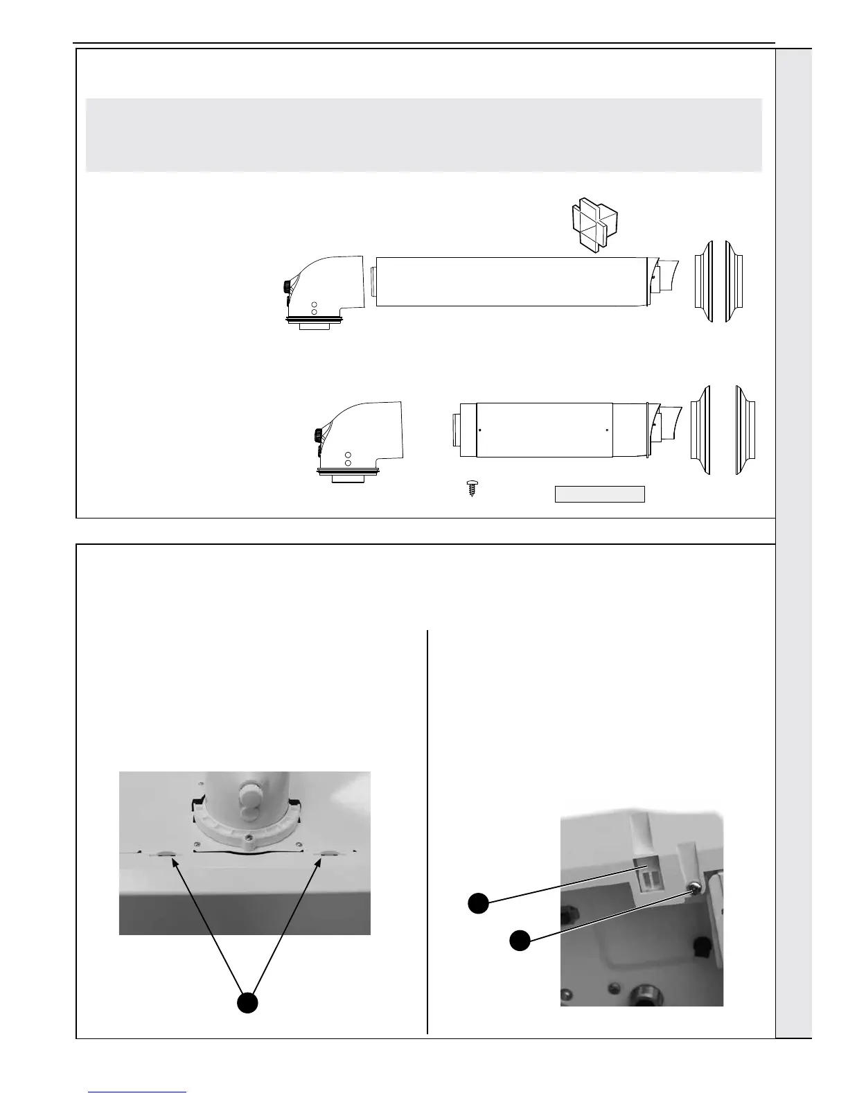
2.3 POD DOOR & FRONT PANEL REMOVAL
POD DOOR
1. Squeeze the two tabs forward and lift the pod door
upwards to remove.
BOILER FRONT PANEL
1. Loosen the 2 screws retaining the front panel.
2. Pull the two clips downwards to disengage.
3. Pull the front panel forward and upwards to remove.
Pack B Contents Telescopic
A Telescopic ue terminal
B Flue turret
C Rubber terminal wall seal
D Screw
E Sealing Tape
F Wall Seal (white)
D
C
A
E
F
B
Pack B Contents Non-Telescopic
A Flue terminal
B Flue turret
C Rubber terminal wall seal
D Cutting Aid
E Wall Seal (white)
UNPACKING CONT’D
1
Note. This ue system incorporates a removable ue outlet nose that utilises a push t location system. This enables the
installation of deector, high level, soft or balcony outlet ue kits without the removal of the whole ‘B’ pack terminal. The
appliance must not be operated without the desired outlet nose correctly tted in place.
Note. Location dimples must be aligned with terminal mounting frame.
1
2
INSTALLATION