11
3.33 RECUPERATOR REPLACEMENT & CLEANING
1. Refer to Section 3.8.
2. Drain the DHW circuit, refer to Section 3.21.
3. Undo the two screws and remove the sump cover
retaining the lower ue manifold.
4. Lift the manifold to clear the bottom sealing gasket
and remove manifold.
5. Remove the fan. Refer to Section 3.9.
6. Remove the burner. Refer to Section 3.4.
7. Disconnect the ue sampling tube.
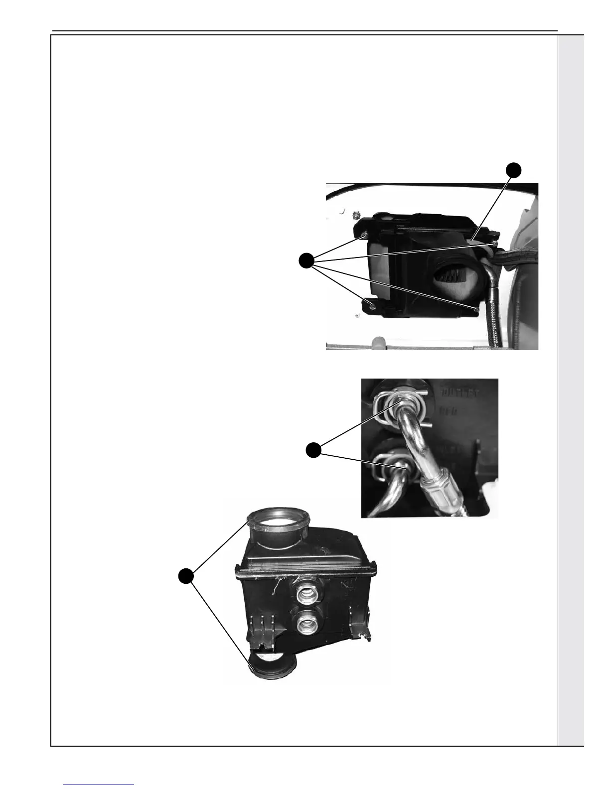
8. Undo the 4 screws retaining the recuperator
assembly to the underside on the boiler top panel.
9. Remove the recuperator from the ue connection by
pulling downwards.
10. Remove the C clips from the recuperator pipes and
disconnect.
11. Fit the new recuperator assembly replacing all ue
seals and O rings with those provided. Ensure both
ue seals are correctly in place before re-assembly.
12. Reconnect the DHW pipes to the recuperator ensuring
both pipes are tted into the correct connection - blue
to the bottom and red to the top.
13. Re-t the recuperator taking care not to trap the ue
sampling tube.
14. Reassemble the boiler in reverse order.
15. Rell the boiler. Refer to Section 2.15.
16. Check the operation of the boiler. Refer to Sections
2.22 & 2.23.
CLEANING
Thoroughly ush the recuperator by pouring water into
the ue inlet or outlet ensuring the full area is covered.
Re-assemble the boiler in reverse order as above.
8
7
10
SERVICING