2.26 HANDING OVER
1.
Hand the User Instructions to the householder and explain his/
her responsibilities under the relevant national regulations.
2. Explain and demonstrate the lighting and shutting down
procedures.
3. The operation of the boiler and the use and adjustment
of all system controls should be fully explained to the
householder, to ensure the greatest possible fuel economy
consistent with the household requirements of both heating
and hot water consumption.
Advise the User of the precautions necessary to prevent
damage to the system and to the building, in the event of the
system remaining inoperative during frosty conditions.
4. Explain the function and the use of the boiler heating and
domestic hot water controls.
Explain that due to system variations and seasonal
temperature uctuations DHW ow rates/temperature
rise will vary, requiring adjustment at the draw off tap. It
is therefore necessary to draw the user’s attention to the
section in the User Instructions titled “Control of Water
Temperature” and the following statement:
“Additionally, the temperature can be controlled by the
user via the draw-off tap: the lower the rate the higher
the temperature, and vice versa”.
5. Explain the function of the boiler fault mode.
Emphasise that if a fault is indicated refer to “Fault Codes” in
the User Guide.
6. Explain and demonstrate the function of time and
temperature controls, radiator valves etc., for the economic
use of the system.
7. If a timer is tted draw attention to the timer User
Instructions and hand them to the householder.
8. Loss of system water pressure
Explain that the dial on the boiler indicates the central
heating system pressure and that if the normal COLD
pressure of the system is seen to decrease over a period
of time then a water leak is indicated. Explain the re-
pressurising procedure and if unable to re-pressurise or if
the pressure continues to drop a registered local heating
installer should be consulted.
9. Explain Boiler restart procedure.
10. After installation and commissioning please complete
the
Commissioning Checklist before
handover to the customer. For IE, its is necessary to
complete a “Declaration of Conformity” to indicate
compliance to I.S. 813:2002.
IMPORTANT
11. A comprehensive service should be carried out ANNUALLY.
Stress the importance of regular servicing by a Gas Safe
Registered Engineer. In IE servicing work must be carried
out by a Registered Gas Installer (RGII).
12. Inform the householder of the guarantee/registration found
within the envelope pack and the requirement to register it to
receive the full benet of the warranty.
After completing the installation and commissioning of the system the installer should hand over to the householder by
the following actions:
2.24 RESTART PROCEDURE
2.25 ACCESSING THE INSTALLER MODE
To restart the boiler, press the RESTART button (I).
To access Installer Mode press the the Function button and “RESTART”
Buttons together for more than 5s.
1. The last 3 faults will be shown
See Section 4.1 for Fault Code descriptions
2. “SL” will be shown
To run the burner at minimum rate press “RESTART”, otherwise
press the Function button.
3. “SH” will be shown
To run the burner at maximum rate press “RESTART”, otherwise
press the Function button.
4. “VF” will be shown
To activate the venting function press “RESTART”, otherwise press
the Function button.
The venting function runs for 5 minutes before automatically
returning to normal operation
The diverter valve moves between CH and DHW every 30s
The Pump alternates between being on for 50s and then off for 10s
5. “dU” will be shown
To move the diverter valve to mid-position for replacement press
“RESTART”, otherwise press Function button.
6. “P1” will be shown
To set the minimum CH pump speed to 100% press “RESTART”,
otherwise press the Function button.
7. “P7” will be shown
To set the minimum CH pump speed to 70% (default) press
“RESTART”, otherwise press the Function button to Exit.
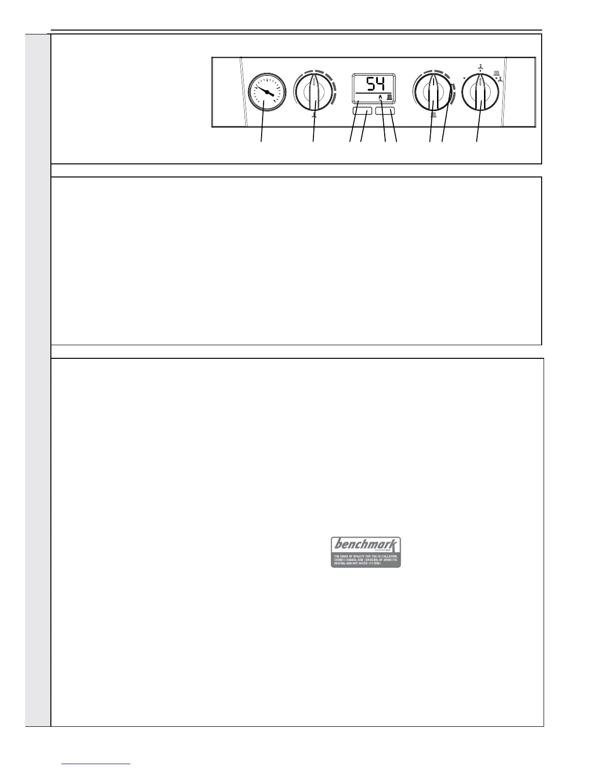
Legend
A. Domestic Hot Water Temperature Knob
B. Central Heating Temperature Knob
C. Mode Knob
D. Boiler Status Display
E. Burner ‘on’ Indicator
F. Central Heating Economy Setting
G. Pressure Gauge
H. Function Button
I. RESTART Button
ºC
MIN MAX MIN
MODE
e
BOILER
OFF
RESTART
MAX
AG D H E
I
B F C
INSTALLATION