3.31 HEAT ENGINE RENEWAL
Refer also to Section 2.1 - ‘Boiler Exploded View’
IMPORTANT
Before starting the removal procedure, protect the gas and electrical controls with a waterproof sheet or plastic bag.
1. Refer to Section 3.8.
2. Drain the boiler. Refer to Section 3.21.
3. Remove the fan / venturi assembly and place on one side.
Disconnect recuperator pipes. Refer to Section 3.33.
4.
Remove the burner and place on one side. Refer to
Section
3.4
.
5. Remove the ignition and detection electrodes. Refer to
Section 3.13 & 3.14.
6. Remove the spark generator. Refer to Section 3.15.
7. Remove the gas valve. Refer to Section 3.16.
8. Remove the expansion vessel. Refer to Section 3.32.
9. Remove the ow and return thermistor. Refer to Sections
3.30 & 3.12.
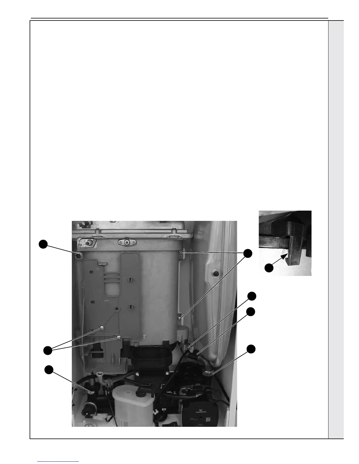
10. Remove the 2 M5 screws retaining the gas valve mounting
bracket and transfer bracket to the new heat exchanger.
11. Undo the pump union nut and remove pipe.
12. Remove the two retaining spring clips and remove pipes.
13. Remove the condensate rubber pipe. Refer to Section
3.18, no. 2.
14. Remove the two heat exchanger xing screws.
15. Remove the Heat exchanger, slide out of location bracket.
16. If replacement sump required: Rotate heat exchanger
assembly 180º. Place new sump onto heat exchanger,
ensuring correct orientation and seal is in place. Then
gently apply pressure to the base of the sump at each tab
xing point and engage tabs onto the heat exchanger.
17. Reassemble in reverse order ensuring the heat exchanger
is correctly positioned in the LH retaining bracket. Replace
any new ‘o’ rings supplied with new heat exchanger and
replacing gaskets or seals if any sign of damage is evident.
When replacing the spring clips located on the return pipe
connection, ensure clip is orientated to correctly match
connecting pipe diameters.
18. Ensure the trap/siphon is lled with water. Refer to
Sections 3.18.
19. Rell the boiler. Refer to Section 2.15.
20. Check operation of the boiler. Refer to Sections 2.22 &
2.23.
14
11
12
10
9
9
12
16
Shown as 180º position
SERVICING