24
CONNECTIONS & FILLING
Note. The domestic hot water ow rate is
automatically regulated to a maximum:
24 = 9.9 l/m (2.2 gpm)
30 = 12.4 l/m (2.8 gpm)
35 = 14.5 l/m (3.2 gpm)
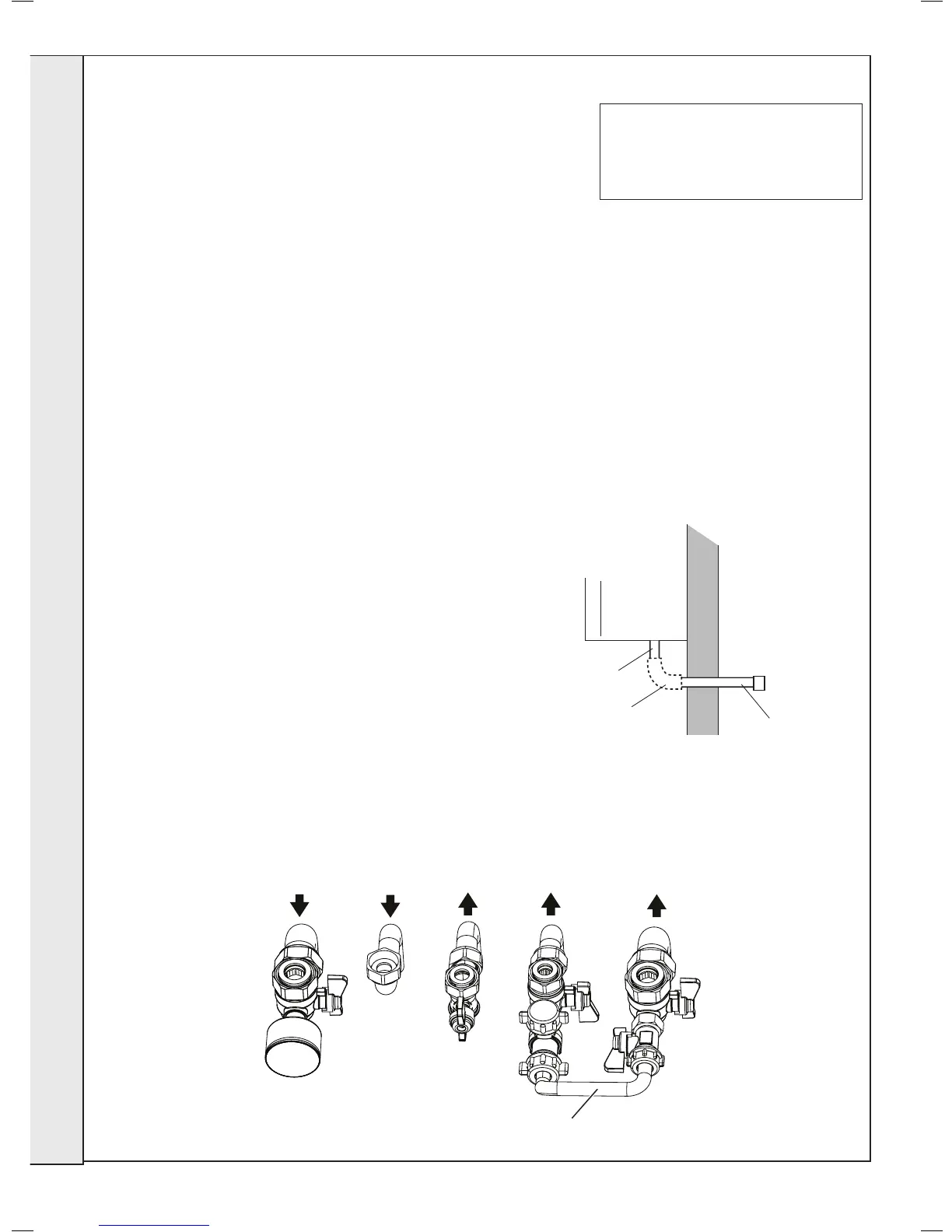
NOTES.
Ensure all boss blanking plugs are removed before connecting hardware. Each
valve must be tted to the correct boss as shown in the picture.
Ensure each union is tted with bre seals provided.
Do not subject any of the isolating valves to heat as the seals may be damaged.
WATER CONNECTIONS CH
1. Connect the CH ow service valve (black handle) and
copper tail provided in the hardware pack to the threaded
boss connection provided at the lower rear of the boiler.
2. Connect the CH rtn. valve (black handle) and copper tail.
3. If connecting the boiler to heating loads in excess of
60,000 Btu/h, connecting ow and return heating systems
pipework must be sized in 28mm diameter at the point
of pipe connection to the boiler tails. use 22mm x 28mm
pipe adaptors as appropriate.
WATER CONNECTIONS DHW
1. Fit the DHW inlet service valve (blue handle) and copper
tail to the threaded boss connection ensuring the seal
provided is correctly located.
2. Fit the DHW outlet pipe tail to DHW outlet connection,
ensuring the seal provided is correctly located.
3. Fit the lling loop provided between the DHW inlet valve
and the CH return valve.
GAS CONNECTION
IMPORTANT. The gas service cock is sealed with a non-
metallic blue bre washer, which must not be overheated when
making capillary connections. Refer to Frame 1 for details of
the position of the gas connection.
For additional gas supply info refer to “Gas Supply” on page 10.
The safety valve connection, located at the bottom right-
hand side of the boiler, comprises a 15mm diameter stub
pipe.
The Installer to provide a compression joint on the end
of the stub pipe. This assists with pipe removal when
servicing.
The discharge pipe should be positioned so that the
discharge of water or steam cannot create a hazard to
the occupants of the premises or damage the electrical
components and wiring.