26
INTERNAL WIRING
The Logic Combi ES boiler comes pre-tted with 1.8m of mains cable.
This must be connected to a permanent live supply and NOT switched
by thermostats/programmers. For installers wishing to change this cable
refer to Frame 35. If the supply cord is damaged, it must be replaced by
the manufacturer, its service agent or similarly qualied persons in order
to avoid a hazard.
The Logic Combi ES boiler comes pre-tted with a link wire between the
room thermostat/Timer connections on the terminal strip. This creates
a permanent call for heat and must be removed when adding a room
thermostat/programmer.
To add thermostat/programmer:
1. Isolate the mains supply to the boiler.
2. Remove the front panel. Refer to Frame 44.
3. Swing the control box down into the servicing position. Refer to Frame
50.
4. Route incoming cables through the grommets in bottom panel (note,
grommets are ‘blind’ and will require puncturing) and secure using
clamps and screws provided in hardware pack.
5. Connect wires to terminal block, see instructions opposite.
6. Swing the control box back up into the operating condition and re-t
the front panel ensuring a good seal is made.
Ideal offer 4 kits as follows:
(see individual kits for installation instructions)
- 24 hour mechanical CH
timer ts into the control box of the boiler. This can be tted
in conjunction with a room thermostat.
- 7 day electronic CH timer
ts into the control box of the boiler. This can be tted
in conjunction with a room thermostat. Features English
language installation help messages.
- Combined 24 hour mechanical timer and room
thermostat with wireless communication to receiver unit
which ts into control box of the boiler.
- Combined 7 day timer and room thermostat
with wireless communication to receiver unit which ts
into control box of the boiler. Features English language
installation help messages. Also OpenTherm Control for
gas consumption saving.
1. Remove link wire between Room stat/timer terminals.
2. Connect room stat across terminals as shown in diagram A -
see Frame 34.
3. If room stat has a neutral connection, connect this to terminal
N (load) in the fused spur.
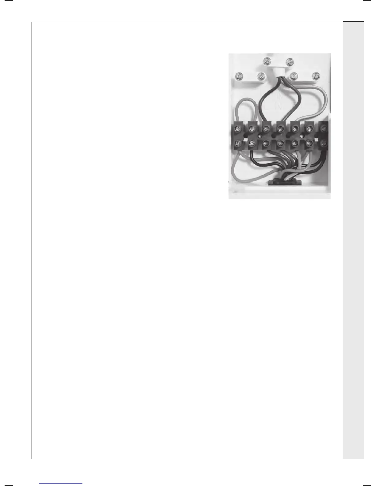
ROOM THERMOSTAT + TIMER - WIRING
1. Remove link wire between Room stat/timer terminals.
2. Connect room stat and programmer in series as shown in
diagram B - see Frame 34.
3. If room stat has a neutral connection, connect this to terminal
N (load) in the fused spur.
FROST THERMOSTAT - WIRING
If parts of the system are vulnerable to freezing or the
programmer is likely to be left off during cold weather, a frost stat
should be tted in conjunction with a pipe thermostat.
1. Position the frost thermostat in a suitable position, i.e. area
vulnerable to freezing.
2. Connect frost stat across terminals marked frost stat as
shown in diagrams A and B - see Frame 34.
INSTALLATION