EasyManuals Logo
Home>IDEAL>Boiler>Logic Combi ES ES24

IDEAL Logic Combi ES ES24 User Manual

IDEAL Logic Combi ES ES24
68 pages
To Next Page IconTo Next Page
To Previous Page IconTo Previous Page
Page #24 background imageLoading...
Page #24 background image
24
INSTALLATION
Logic Combi ES - Installation and Servicing
FLUE OUTLET
rf8394-1
690mm
Fixed
300mm
min
20
FLUE TERMINAL POSITION
rf8393-1
300mm
min
300mm
min
625mm
Fixed
Flat roof - with structure
The terminal should be positioned so that products of
combustion can safely disperse at all times.



Minimum dimensions are shown below
RF9807
A
A
B
A
A = 600mm
B = 2000mm
The flue terminal shall not penetrate the shaded area of the roo
f
Note.
The equivalent ue length
resistance of the elbow kits are:
90
o
elbow kit = 1m
45
o
elbow kit = 0.6m
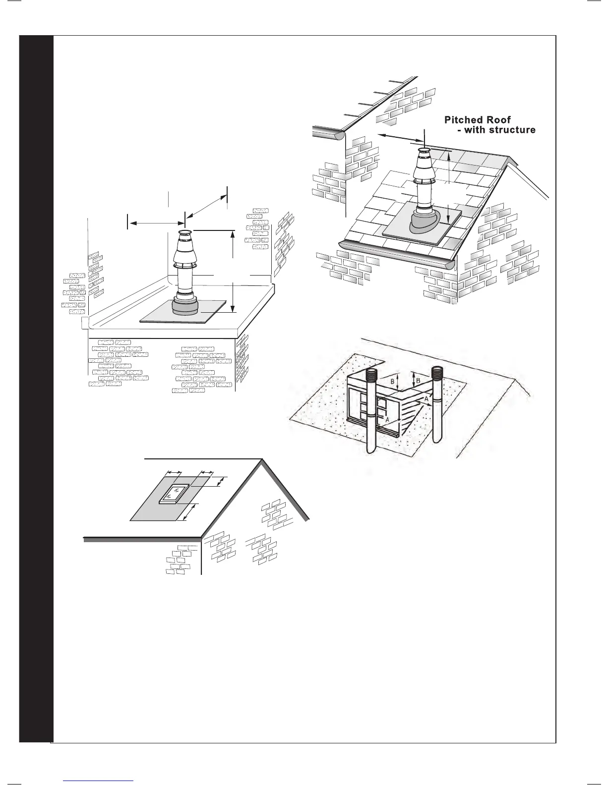
If chimney penetrates dotted area such that A is less
than 300mm, B shall not be less than 300mm.
Where two or more vertical fanned draught chimney congurations terminate in close
proximity at the same height, they shall be separated by at least 300mm. Where any
one vertical outlet is more than 300mm above the other, then they shall be separated
by at least 1 500mm.
Where any vertical fanned draught chimney conguration outlet is within 2000mm
measured horizontally of an opening window, then it shall be at least 300mm above
the opening.

or opening

Questions and Answers:

Question and Answer IconNeed help?

Do you have a question about the IDEAL Logic Combi ES ES24 and is the answer not in the manual?

IDEAL Logic Combi ES ES24 Specifications

General IconGeneral
BrandIDEAL
ModelLogic Combi ES ES24
CategoryBoiler
LanguageEnglish

Related product manuals