The wall mounting template is located on the internal protective
packaging. The template shows the position of the xing and rear
ue centre holes for a standard installation
Care MUST be taken to ensure the correct holes are drilled.
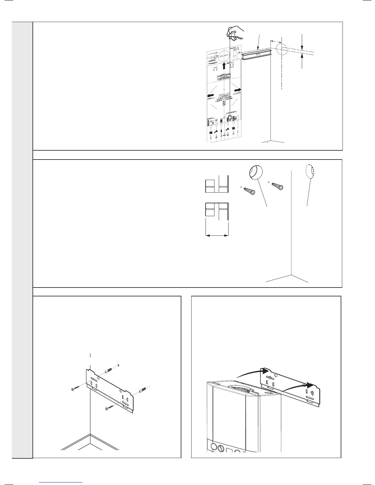
1. Tape template into the required position, ensuring its squareness
by hanging a plumbline as shown.
2. If tting a side ue, extend the ue centreline onto the side by
155mm on a standard wall x or 200mm if using a stand-off
bracket.
3. Mark the following on to the wall:
a The selected group of wall mounting screw holes.
b. The centre position of the ue duct. Marking both the centre
and the circumference of the ue duct.
4. Remove the template plate from the wall.
10
WALL MOUNTING TEMPLATE
11
PREPARING THE WALL
IMPORTANT.
Ensure that, during the cutting operation, masonry falling
outside of the building does not cause damage or personal
injury.
1. Cut the ue hole (preferably with a 5” core boring tool),
ensuring that the hole is square to the wall.
Both wall faces immediately around the cut hole should be
at.
2. Drill 2 mounting holes (marked from template) with a 7.5mm
/ 8mm masonry drill and insert the plastic plugs, provided,
for the wall mounting plate.
3. Locate 2 No.14 x 50mm screws in the wall mounting plate
(one at each side, in any of the 3 holes provided at each
side) and screw home. Ensure mounting bracket is level.
13
MOUNTING THE BOILER
1. Ensure the plastic plugs are removed from both the CH
and DHW connections before mounting the boiler.
Note. boiler may contain residual water.
2. Lift the boiler onto the wall mounting plate (refer to the
Introduction section for safe handling advice), locating it
over the two tabs.
12
FITTING THE WALL MOUNTING PLATE
Screw the wall mounting plate to the wall using 2 wall plugs
(previously tted) with the 2 screws provided.
Choose one of the 2 sets of slots in left and right bank.
Ensuring that at least one of the screws is tted into a top slot
and the mounting bracket is level.