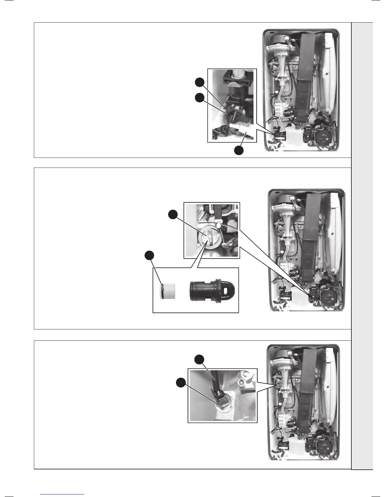
1. Refer to Frame 43.
2. Drain down the boiler. Refer to Frame 57.
3. Unplug the electrical lead.
4. Unscrew the thermistor (to facilitate removal a
13mm socket spanner should be used).
5. Fit the new thermistor using the sealing
washer provided.
6. Reassemble in the reverse order.
7. Rell the boiler. Refer to Frame 24.
8. Check the operation of the boiler. Refer to
Frames 32 & 33.
67
FLOW THERMISTOR REPLACEMENT
65
CH WATER PRESSURE SWITCH REPLACEMENT
1. Refer to Frame 43.
2. Drain the boiler. Refer to frame 57.
3. Pull off the two electrical connections.
4. Using a suitable tool, pull out the metal retaining clip.
5. Carefully withdraw the pressure switch.
6. Fit the new pressure switch and re-assemble in reverse
order.
7. Rell the boiler.
8. Check operation of the boiler. Refer to Frames 32 & 33.
3
4
5
66
3
1. Refer to Frame 43.
2. Isolate the DHW supply.
3. Turn the housing anti clockwise and
pull forward to remove the cartridge. Be
aware of water spillage.
4. Using a pair of pliers, pull out the plastic
lter/ow regulator.
5. Clean or replace lter as necessary.
6. Reassemble in reverse order.
7. Re-instate the DHW supply and check for
leaks.
8. Check operation of the boiler. Refer to
Frames 32 & 33.
4
4
3
 Loading...


