57
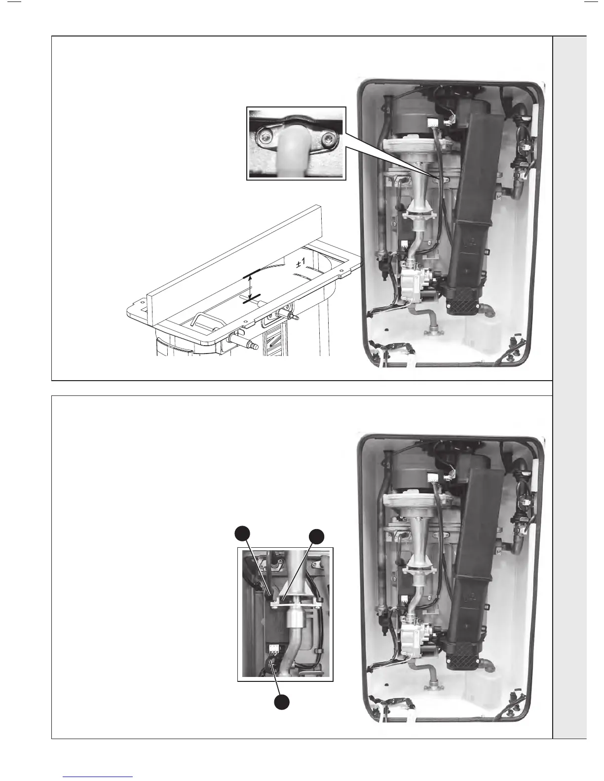
FLAME DETECTION ELECTRODE REPLACEMENT
58
SPARK GENERATOR REPLACEMENT
1. Refer to Frame 51.
2. Disconnect the leads from the spark
generator
3. Remove the single M5 Screw
securing the spark generator to the
gas valve mounting bracket.
4. Lift the spark generator up and out of
the bottom retaining moulding.
5. Fit the new spark generator and re-
assemble in reverse order ensuring
that the the earth lead is replaced
6. Check operation of the boiler .Refer
to Frames 40 & 41.
Flame Detection Electrode
1. Refer to Frame 51.
2. Remove the burner. Refer to Frame 54.
3. Unplug the ame detection lead from the
electrode.
4. Remove the 2 screws retaining the detection
electrode.
5. Remove the electrode.
6. Fit the new ame detection electrode (check
dimension as shown below), using the new
gasket supplied.
7. Reassemble in reverse order.
8. Check the operation of the boiler. Refer to
Frames 40 & 41.
3
2
2
SERVICING
 Loading...


